Adam,
There are several very useful prior threads on Powermatic VFD replacement, and I would strongly encourage you to search for them and review. No need to reinvent the wheel.
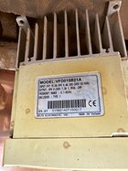
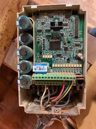
The aluminum fin contraption that was between the old VFD and the headstock was useful for cooling the VFD. Most new VFDs come with a fan as Darryl suggested and the fins are not required. HOWEVER, hidden in the fins is the 3520a braking resister. You may want to remove it and mount it along with the new VFD. (It's stuck on with foam double sided tape and can seem surprisingly solidly fixed) Some newer VFDs include a function that makes the braking resister superfluous, but I'm a belt and suspenders kinda guy.
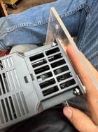
One aspect not generally covered in prior VFD threads is that the holes in the headstock for attaching the VFD will probably not be right for the new VFD. You will have to rig up an interface panel or drill and tap holes in the headstock. An interface panel could be as simple as a 1/8+" sheet of aluminum into which you drill holes that match the headstock and holes that match the vfd. I forget the reason, but wood is not a desirable interface in this setting.