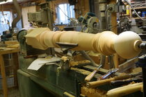
This is a heavily modified Powermatic 90 asking $1,000.00 or best offer - Modifications listed below in the approximate order they were accomplished. I am located near Park Rapids MN, which is about 200 miles from the Minneapolis/St. Paul Metro area and 90 miles east of Fargo ND. I could possibly move it to the metro area, but no further then that and I would have to be compensated for the cost.
- Height blocks 3" high giving it an 18" turn diameter.
- The height block on the tailstock has a cam lock added to replace the stock locking bolt that was limited due to flexing of the iron around the hole.
- The original 1HP motor was replaced with a 1 1/2 HP 230 Volt 1125 RPM 3Ph Baldor motor.
- The VFD was added to provide electronic variable speed and is configured to drive up to 90 Hz, it has been about 12 years since it was installed and never had any problems.
- Notes concerning the motor and VFD. The motor is rated for constant torque up to it's rated voltage & frequency and since the motor is 6 pole it has a higher torque then the more common 4 pole 1725 RPM motor. The VFD will maintain the voltage/frequency ratio up to the rated 230 Volts 60Hz and the from there the torque curve drops off. The settings such as top frequency, accel/decel are easily changed if so desired.
- The variable pitch belt drive system was initially left in place as seen in this picture, but has been removed and replaced with multi rib belt system the same as used in modern lathes.
- The headstock spindle thread has been changed from 1 1/2-8 to the now more common 1 1/4-8 thread.
- The lathe is mounted on a frame made of 2" X 4" rectangular steel tube with casters on both ends.
- There is a short bed extension permanently mounted.
- There is a removable long bed extension that will give about 8 foot 6 inches between centers.
- The project mounted is 1 of 2 6 foot barber poles made from a 12 foot 8 x 8 of white pine that I milled from a locally cut saw log.
