• Congratulations to Rick Moreton, People's Choice in the July 2025 Turning Challenge (click here for details)
  • Congratulations to Michael Foster for "Costa II" being selected as Turning of the Week for July 28th, 2025 (click here for details)
  • Welcome new registering member. Your username must be your real First and Last name (for example: John Doe). "Screen names" and "handles" are not allowed and your registration will be deleted if you don't use your real name. Also, do not use all caps nor all lower case.

Powermatic VFD replacement

Joined
May 4, 2010
Messages
2,851
Likes
2,313
Location
Bozeman, MT
Sorry to raise this dead horse for beating again.

We're nearly done replacing the VFD on one of our high school's Powermatic 3520B lathes, but there are no wires for a braking resistor. Do some of the Powermatics not require a braking resistor? If they all do, any suggestions on where to look for the wires? Nothing in the control bundle, nothing visible through the panels in the headstock, except the "pink" and red wires which connect to black and white wires presumably from the RPM display.

Thanks for the help.
 
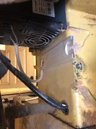
The braking resistor is in your old delta drive, I pulled mine and stuck it under my new drive. I'll send you a picture of it. I thought the same as you then I looked at the manual parts breakdown and it shows part 80 near the VFD and that's where I found mine. Your wires may still be connected to the old drive.

IMG_1422.jpg
 
Last edited:
My 3520B resistor is mounted inside the headstock on the back wall, just to the left of the belt and motor pulley. It's part of an aluminum heat sink 1 1/4" by about 5" long.
 
My 3520B resistor is mounted inside the headstock on the back wall, just to the left of the belt and motor pulley. It's part of an aluminum heat sink 1 1/4" by about 5" long.
Joe, I just reread John Coppola's article in the tips and tricks area and he does not mention moving his brake resistor. If you look at his pictures of the wires that connect to the connector ports '+' and 'PB' and follow them, they enter the back of the headstock so his was located the same as yours. When I changed my VFD, and was rewiring, I looked for my resistor wires and they were gone... then I found them disconnected but still in the old drive. My resistor was stuck on the wall of the old drive in the heat sink compartment.
 
Last edited:
There were two wires I thought were the braking resistor, but which ultimately led to the fins on the heat dissipater. The wire was just a loop tucked into the space and it never occurred to me that they incorporated the braking resistor into the heat sink. I may have to buy a new one, as I pulled the wires out of the old one while investigating.

Thanks, guys.
 
It's not that much of an effort to look in either place for the brake resistor, I actually looked down through the cooling air passageways on the old Delta drive and located mine, but being curious, I e-mailed Powermatic and asked if there was a manufacturing date, or different assembly locations that would determine where the brake resistor is located in the 3520B. Hopefully I will get an answer next week and I'll pass it on and if it is good information maybe get it put in the electrical section of the Mustard Monster site...
 
This may be a little off topic but, here goes:

I am replacing the VFD on my 4224 with an after market inverter and have just realized that the new VFD calls for a 200 ohm 250 W braking resistor. The original braking resistor reads about 80 ohms, so I am awaiting (with bated breath) the arrival of a new resistor (from China); that wait is nearly a month.

In the meantime, what is the likelihood that, if I go ahead an set up the new VFD without the braking resistor attached, will the new VFD become burnt toast?

Just a guess, please. I know what the braking resistor is and what it does, ergo, it does not seem very likely to me.
Just increase the Deceleration time. The breaking resistors are only there to absorb the overload created by rapid deceleration, but without them the drive should sense an overload and shut itself down if the deceleration is to fast.
 
Just increase the Deceleration time. The breaking resistors are only there to absorb the overload created by rapid deceleration, but without them the drive should sense an overload and shut itself down if the deceleration is to fast.
I don't understand "without them the drive should sense an overload and shut itself down if the deceleration is to fast."
Are you saying it the VFD will raise an error? I can live with that.

What if I used the 80 ohm resistor that I have while I wait for the 200 ohm resistor to be delivered?
It occurs to me that with the smaller resistor, not as much heat/power will be dissipated so the smaller resistor would be safe and the deceleration would take a longer period.
Is that reasoning, reasoning?

Can I safely program the VFD with either no braking resistor or the 80 ohm resistor?

I appreciate you.
 
If you can find a couple of resistors, you could solder them in series to get your 200 ohms.
You could also use a variable resistor and use an ohmmeter to determine the position to attain 200 ohms.
 
I found a braking resistor for the inverter on my lathe on eBay but I never installed it. As Don indicated the resistor is more of a nice to have feature, but certainly not essential for a woodturning lathe. The resistor would be needed if you had a very short deceleration ramp time, but a short deceleration time would lead to a much more significant problem ... namely, the chuck unscrewing.
 
Seems to me that as you lower the resistance you increase the current dissipation value and decrease the deceleration time value. 80 ohms should allow a faster deceleration rate and higher current than 200 ohms, so the resistor would set the max deceleration rate if the time value programmed in the VFD was minimum or zero. The 250-watt rating should also be considered. The values specified by the manufacturer probably had a little thought or data behind the selection. Sorry, I don't know enough to answer your question, just providing a few thoughts.
 
Seems to me that as you lower the resistance you increase the current dissipation value and decrease the deceleration time value. 80 ohms should allow a faster deceleration rate and higher current than 200 ohms, so the resistor would set the max deceleration rate if the time value programmed in the VFD was minimum or zero. The 250-watt rating should also be considered. The values specified by the manufacturer probably had a little thought or data behind the selection. Sorry, I don't know enough to answer your question, just providing a few thoughts.

The resistance value doesn't control the braking time, but it might be a factor in determining limits on braking time. It is for impedance matching for maximum braking efficiency.

Have you tried to source the resistor from DigiKey or Mouser?

While you can find power resistors at Mouser and DigiKey, they aren't the best solution unless your other hobby is building electronic assemblies. Also, some braking resistor modules contain active components in addition to passive power resistors.
 
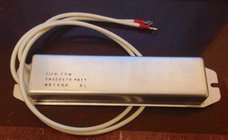
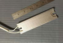
For anyone who is looking for theirs, the braking resistors I have seen in a pair of 3520As and a pair of 3520Bs are either a slim aluminum sled, about 3/16" tall, 1.2" wide and 4" long which is mounted with double sided foam tape in the heat sink adjacent to the VFD, or an aluminum box about 1" wide, 1.5" deep snf 4" long mounted with screws inside the headstock. (Note: measurements are eye ball estimates)

It seems to me, in my electronic ignorance, that the resistor needs to match the motor more than the VFD. Couldn't the questioner simply reuse the braking resistor from the prior VFD, which worked just fine with the lathe/motor she has?
 
Here is the braking resistor that I found on eBay for the Toshiba S11 inverter in my Robust American Beauty. The resistance is 75 ohms and 120 watts maximum power. The dimensions are approximately 6" X 1½" X ¾". One of these days I might even install it.

braking resistor.jpg
 
The braking resistor is there to dissipate the excess voltage on the DC bus (inside the inverter) created when the inverter reverses the voltage to stop the motor. A longer the deceleration means a lower voltage spread over a longer time interval which then does not create as much heat/voltage for the resistor to dissipate.
I’ve seen them glow Cherry red on CNC machines.
 
Back
Top