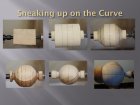
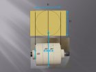
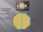
There seems to be considerable interest lately in a certain structured procedure for turning spheres by hand. Apparently, Sören Berger and Al Hockenbery independently discovered the basic concept and both have popularized it for several years. The procedure involves first turning a cylinder with a length and diameter equal to the diameter of the desired sphere. The outline of this cylinder will appear as a square. The corners of this square then are sliced off in a straight line to produce an 8-sided outline that approximates a sphere. Optionally, one can continue the process by turning off the new corners to form a 16-sided approximation, and this can be continued further into finer approximations if desired. The final result, from whichever level, can be smoothed out by eye to produce a pretty good sphere.
The following three images illustrate the sequence for the 16-sided approximation.

I personally have used this method many times to turn spherical ornaments, and spheres that become the bowls of one-piece ladles and spoons, and find it fast and convenient. (I generally stop at the 8-sided stage.) Although I have never used a sphere-turning jig, I expect that this method is far faster (and certainly a lot cheaper) than using a jig, if you do not require high accuracy. Furthermore, it strikes me that this method would be a time-efficient way of roughing out a sphere before using the jig.
The catch (no, not that kind) is that in order to make these cuts, you first need to determine where to mark the boundaries of the cuts. At each stage, you need to mark the piece at a particular distance each side of the existing corners. In the first stage, which produces an 8‑sided approximation, the required distance is 0.293 times the diameter of the sphere. In the second stage, which produces a 16-sided approximation, the required distance is 0.108 times the diameter of the sphere. Unfortunately, unless you have a calculator in the shop and a decimal ruler or calipers, this calculation and measuring can be challenging. One option is to purchase the $70.00 multi-calipers measuring tool from Sören Berger that, when set to the diameter of the sphere, provides direct indications of the offsets needed for Stage 1 and Stage 2. For those who cannot justify the cost of this tool, I would like to offer a simple, fast, no-cost, no-math alternative that anyone can use. This method makes use of a simple design graph, as shown below.
The first graph, when printed, will let you measure the desired quantities directly using calipers or a strip of paper, for spheres up to just over 3-1/2 inches in diameter; an extension plot follows that will go up to 6 inches. Because the measurements are proportional, relative to the selected diameter, these charts are dimension free, and the figure can be printed at any size as long as it covers the largest sphere diameter desired.


To use the graphs, first set your calipers to the diameter of the desired sphere. Then, hold the calipers horizontally and slide them down the graph until they exactly span the distance between the reference line R and the diameter line D. Mark this vertical position on the graph with a horizontal line parallel to the rulings. For the offset A1, that is required for the first stage, use your calipers (or a strip of paper) to measure the distance from the line R to the line A1 along the horizontal line and use it to mark cut lines on the work piece at that distance each side of each of the corners. To obtain the offset A2 for the second stage, do exactly the same, except copy the distance between line R and line A2. Similarly, for a third stage, copy the distance from line R and line A3. When performing the cuts across a corner at any stage, be sure to leave a vestige of the original guide lines showing. These mark the new corners that will be removed in the next stage. Also, to avoid confusion, it will be helpful to change marking colors between stages.
To draw a graph for yourself that will accommodate spheres of up to 4 inches diameter, obtain a sheet of quadrille paper (I used ¼” ruled paper, but any will work) and mark a point near the top left of the sheet, as shown in the first figure, and draw a vertical line down to one of the rulings near the bottom of the sheet. This is the reference line R. Then draw a horizontal base line as shown. Measuring from the R line along the base line, mark points at 0.20” (7/32”), 0.43 (7/16”), 1.17” (1-3/16”), and 4.00 inches. Alternatively, if you prefer to span diameters up to 6 inches on a single graph, at possibly some loss of accuracy at small diameters, make the marks at 0.30” (5/16”), 0.65” (5/8”), 1.76” (1-3/4”), and 6.00”. The fractional measurements shown are close approximations to the actual decimal values for those who do not have decimal rulers. If you need to turn larger spheres you can easily extend the range of the graph. Carefully align a second sheet of quadrille paper with the original piece, offsetting it to the right if necessary, and extend the lines R, A1, A2, A3 and D onto the new sheet.
The length of the line R is not critical; however the longer it is for a given maximum value of D, the more accurate the procedure will be (the measurements of A1, A2, and A3 will be less sensitive to small errors in vertical positioning of the calipers on the graph). I wanted to be able to handle up to 4-inch spheres with one sheet of paper, and this led to the first graph shown. (Note that the publication process has led to slight shrinkage of the figures.) As noted above, in principle, this procedure can be extended to additional stages (more sides), but unless the sphere is very large, errors in measurement and marking will tend to blur the benefits. For those interested in trying, further values of A are easily added to the graph. The A line for each new stage moves halfway in toward the R line from the preceding A line. In other words, the line for A4 will lie almost exactly halfway between the line A3 and the reference line R, and so on for further stages.
After the publication of the original version of this article, I discovered an interesting fact that makes it even easier to continue on to a third Stage or higher. For stages three and higher, the required value of A is almost exactly one-fourth the width of the current faces. Thus by eye one easily mark the center of a current face and then by eye divide the two halves in two to obtain the positions of cut lines needed for that face. I also found that when dealing with short straight-line cuts in the final Stages of the process, a square-ended scraper provides the fine control needed better than does a gouge.
Mathematical Basis for the Procedure
Consider the profile of the turning as viewed from the front. The procedure begins with a square profile of height and length equal to the diameter of the eventual sphere. Stage 1 of the procedure slices off each corner of the square and replaces it with two corners a distance A1 on either side of the old corner and produces an 8-sided figure. Examination reveals that A1 is equal to half the difference between the length of a side of the old square and the length of a side of the new 8-sided figure. Furthermore, this relationship is true for all subsequent stages as well. That is, the value of A needed in a given stage is equal to half the difference between the length of a side before performing that stage and the length of a side produced by that stage. Applying a bit of elementary trigonometry, we find:

The following three images illustrate the sequence for the 16-sided approximation.
I personally have used this method many times to turn spherical ornaments, and spheres that become the bowls of one-piece ladles and spoons, and find it fast and convenient. (I generally stop at the 8-sided stage.) Although I have never used a sphere-turning jig, I expect that this method is far faster (and certainly a lot cheaper) than using a jig, if you do not require high accuracy. Furthermore, it strikes me that this method would be a time-efficient way of roughing out a sphere before using the jig.
The catch (no, not that kind) is that in order to make these cuts, you first need to determine where to mark the boundaries of the cuts. At each stage, you need to mark the piece at a particular distance each side of the existing corners. In the first stage, which produces an 8‑sided approximation, the required distance is 0.293 times the diameter of the sphere. In the second stage, which produces a 16-sided approximation, the required distance is 0.108 times the diameter of the sphere. Unfortunately, unless you have a calculator in the shop and a decimal ruler or calipers, this calculation and measuring can be challenging. One option is to purchase the $70.00 multi-calipers measuring tool from Sören Berger that, when set to the diameter of the sphere, provides direct indications of the offsets needed for Stage 1 and Stage 2. For those who cannot justify the cost of this tool, I would like to offer a simple, fast, no-cost, no-math alternative that anyone can use. This method makes use of a simple design graph, as shown below.
The first graph, when printed, will let you measure the desired quantities directly using calipers or a strip of paper, for spheres up to just over 3-1/2 inches in diameter; an extension plot follows that will go up to 6 inches. Because the measurements are proportional, relative to the selected diameter, these charts are dimension free, and the figure can be printed at any size as long as it covers the largest sphere diameter desired.


To use the graphs, first set your calipers to the diameter of the desired sphere. Then, hold the calipers horizontally and slide them down the graph until they exactly span the distance between the reference line R and the diameter line D. Mark this vertical position on the graph with a horizontal line parallel to the rulings. For the offset A1, that is required for the first stage, use your calipers (or a strip of paper) to measure the distance from the line R to the line A1 along the horizontal line and use it to mark cut lines on the work piece at that distance each side of each of the corners. To obtain the offset A2 for the second stage, do exactly the same, except copy the distance between line R and line A2. Similarly, for a third stage, copy the distance from line R and line A3. When performing the cuts across a corner at any stage, be sure to leave a vestige of the original guide lines showing. These mark the new corners that will be removed in the next stage. Also, to avoid confusion, it will be helpful to change marking colors between stages.
To draw a graph for yourself that will accommodate spheres of up to 4 inches diameter, obtain a sheet of quadrille paper (I used ¼” ruled paper, but any will work) and mark a point near the top left of the sheet, as shown in the first figure, and draw a vertical line down to one of the rulings near the bottom of the sheet. This is the reference line R. Then draw a horizontal base line as shown. Measuring from the R line along the base line, mark points at 0.20” (7/32”), 0.43 (7/16”), 1.17” (1-3/16”), and 4.00 inches. Alternatively, if you prefer to span diameters up to 6 inches on a single graph, at possibly some loss of accuracy at small diameters, make the marks at 0.30” (5/16”), 0.65” (5/8”), 1.76” (1-3/4”), and 6.00”. The fractional measurements shown are close approximations to the actual decimal values for those who do not have decimal rulers. If you need to turn larger spheres you can easily extend the range of the graph. Carefully align a second sheet of quadrille paper with the original piece, offsetting it to the right if necessary, and extend the lines R, A1, A2, A3 and D onto the new sheet.
The length of the line R is not critical; however the longer it is for a given maximum value of D, the more accurate the procedure will be (the measurements of A1, A2, and A3 will be less sensitive to small errors in vertical positioning of the calipers on the graph). I wanted to be able to handle up to 4-inch spheres with one sheet of paper, and this led to the first graph shown. (Note that the publication process has led to slight shrinkage of the figures.) As noted above, in principle, this procedure can be extended to additional stages (more sides), but unless the sphere is very large, errors in measurement and marking will tend to blur the benefits. For those interested in trying, further values of A are easily added to the graph. The A line for each new stage moves halfway in toward the R line from the preceding A line. In other words, the line for A4 will lie almost exactly halfway between the line A3 and the reference line R, and so on for further stages.
After the publication of the original version of this article, I discovered an interesting fact that makes it even easier to continue on to a third Stage or higher. For stages three and higher, the required value of A is almost exactly one-fourth the width of the current faces. Thus by eye one easily mark the center of a current face and then by eye divide the two halves in two to obtain the positions of cut lines needed for that face. I also found that when dealing with short straight-line cuts in the final Stages of the process, a square-ended scraper provides the fine control needed better than does a gouge.
Mathematical Basis for the Procedure
Consider the profile of the turning as viewed from the front. The procedure begins with a square profile of height and length equal to the diameter of the eventual sphere. Stage 1 of the procedure slices off each corner of the square and replaces it with two corners a distance A1 on either side of the old corner and produces an 8-sided figure. Examination reveals that A1 is equal to half the difference between the length of a side of the old square and the length of a side of the new 8-sided figure. Furthermore, this relationship is true for all subsequent stages as well. That is, the value of A needed in a given stage is equal to half the difference between the length of a side before performing that stage and the length of a side produced by that stage. Applying a bit of elementary trigonometry, we find:


