-
July 2025 Turning Challenge: Turn a Multi-axis Weed Pot! (click here for details) -
Congratulations to James Seyfried for "NE Red Oak II" being selected as Turning of the Week for July 21, 2025 (click here for details) -
Welcome new registering member. Your username must be your real First and Last name (for example: John Doe). "Screen names" and "handles" are not allowed and your registration will be deleted if you don't use your real name. Also, do not use all caps nor all lower case.
You are using an out of date browser. It may not display this or other websites correctly.
You should upgrade or use an alternative browser.
You should upgrade or use an alternative browser.
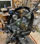
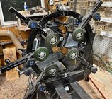
Steady rest Critique requested
- Thread starter Albert Heemskerk
- Start date
Albert, I am far from any kind of expert on steady rest, so these comments take with a grain of salt. Anything that works is good. What I see often is people put an arm in the 12 o’clock position. I put mine at 9 o’clock, around 2 o’clock and 5 o’clock. That is because if you use a laser or camera for hollow forms the 12 o’clock position would be in the path of those. You want to go under the steady rest with the laser instead of over it as you loose some sharpness of the laser and more movement due to vibration when higher. Just my take.I like the 9 o’clock position for the other arm as a preference since doing hollow forms it is in direct opposition the the cutter force. I would also round off the arms just for looks, non functional.
Last edited:
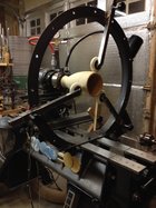
You must be above average height, curious who made ur lathe, steady rest looks strudy, lathe with your skills produces nice curlings,like your backstop
Looks like you need one more arm and wheel. The three on there are almost all touching and looks like a large open spot in the back where you will need support from pushing with a tool on the front. Trust me I am no expert, just what makes sense to me.
I know little about this but I would think you want the 3 wheels to converge at the lathe center at all times, even when a work piece is in place. In the photo that doesn't appear to be the case. Could just be how you oriented them before tightening. Also, the plywood used with the wheels looks a bit thin and may flex too much when turning.
William can we have a picture of your steady rest?Albert, I am far from any kind of expert on steady rest, so these comments take with a grain of salt. Anything that works is good. What I see often is people put an arm in the 12 o’clock position. I put mine at 9 o’clock, around 2 o’clock and 5 o’clock. That is because if you use a laser or camera for hollow forms the 12 o’clock position would be in the path of those. You want to go under the steady rest with the laser instead of over it as you loose some sharpness of the laser and more movement due to vibration when higher. Just my take.I like the 9 o’clock position for the other arm as a preference since doing hollow forms it is in direct opposition the the cutter force. I would also round off the arms just for looks, non functional.
Paul
Does it do what you want to it to? If so it's great! (Mine is very similar)
I'm bigger than your average bear, so I need tools that are higher off the ground. The lathe is a Nova DVR. The backstop is going to be redone with clear sheet material, I've lost all natural light from the window.You must be above average height, curious who made ur lathe, steady rest looks strudy, lathe with your skills produces nice curlings,like your backstop
In my eagerness to try it out, I've mounted it backwards, the double wheels are meant to go on the back side of the workpiece. That will cover the forces generated by the work piece I think. If I'm wrong, let me know.Albert, I am far from any kind of expert on steady rest, so these comments take with a grain of salt. Anything that works is good. What I see often is people put an arm in the 12 o’clock position. I put mine at 9 o’clock, around 2 o’clock and 5 o’clock. That is because if you use a laser or camera for hollow forms the 12 o’clock position would be in the path of those. You want to go under the steady rest with the laser instead of over it as you loose some sharpness of the laser and more movement due to vibration when higher. Just my take.I like the 9 o’clock position for the other arm as a preference since doing hollow forms it is in direct opposition the the cutter force. I would also round off the arms just for looks, non functional.
PaulWilliam can we have a picture of your steady rest?
Paul
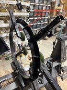
My steady rest was made to the Nichols design. I searched SMC tor the plans. It is made from a steel flange and square steel tubing. I made mine as a 4 wheel design. I did not want a wheel at the 12 o’clock position. I initially made it for my Laguna 18” swing. When I got my Robust AB that is a 25” swing I had to add 3 1/2” to the base made from wood to keep it centered. I wasn’t going to make a new steady rest as my biggest hollow form I have done was 16”. And this steel steady rest is somewhat heavy. My steady rest with a 4 wheel design has the wheels at 7, 10, 2, and 5 o’clock positions. I also made a 5th wheel that could be installed at any open hole on the steel flange.
I normally use it with 4 wheel as shown in this first picture, 7, 9, 2, and 5 o’clock positions. It is already overkill, but I have the wheel for the 10 o’clock position if I wanted to put that one in.
Didnt have a picture with a piece, so I just set on the lathe. Excuse the mess I just got done turning.
I normally use the steady rest in this configuration with 4 wheels installed.

I could install a 5th wheel and it is really overkill at this configuration.

Last edited:
Albert, 3 wheels somewhat equally space around will work. The point I was making was if you have a wheel at the 12 o’clock position it will interfere with using a laser or camera. You could rotate that arm and avoid the 12 o’clock position and use the 11 o’clock position instead with a three wheel design. I have a 4 wheel design and use set the wheels as described I post #10.In my eagerness to try it out, I've mounted it backwards, the double wheels are meant to go on the back side of the workpiece. That will cover the forces generated by the work piece I think. If I'm wrong, let me know.
I made a 3 wheel model switched to a 2 oneway bowl steadyes, then finnally with oneway 1 wheel steady, if properly set up with the 1 wheel supporting the point of contact with tool and inside hf it is enough, imo
Properly set up the hf runs true or rim is perfect circle
Properly set up the hf runs true or rim is perfect circle
I need to learn how to weld.....
I don’t see anything wrong with your steady. If the top wheel doesn’t interfer with your laser/camera it’s not a problem. I find mine winds up being offset to the side wall anyway, so offsetting the wheel may not be critical. Use it and find out - not that big of a deal to move it. It just depends on the shape and size of the hollow forms you turn.
I built from the same - or very similar - plans as Williams. I used only three wheels, equally spaced but offset from the vertical by 10 degrees To allow the laser - now camera - to clear. It works great. I hadn’t welded in over 40 years (since college days), but I borrowed a decent mig welder from a friend who gave me a quick demo and turned me loose. It works great - don’t look too close at the welds - they’re ugly but functional.
I built from the same - or very similar - plans as Williams. I used only three wheels, equally spaced but offset from the vertical by 10 degrees To allow the laser - now camera - to clear. It works great. I hadn’t welded in over 40 years (since college days), but I borrowed a decent mig welder from a friend who gave me a quick demo and turned me loose. It works great - don’t look too close at the welds - they’re ugly but functional.

Last edited:
Goo job. My welds were with my HF flux core. They hold, but very likely a lot more ugly.I don’t see anything wrong with your steady. If the top wheel doesn’t interfer with your laser/camera it’s not a problem. I find mine winds up being offset to the side wall anyway, so offsetting the wheel may not be critical. Use it and find out - not that big of a deal to move it. It just depends on the shape and size of the hollow forms you turn.
- don’t look too close at the welds - they’re ugly but functional.View attachment 50970
I like your sanding disc holder. I’m going to copy that.
William, Did you fabricate the flange or purchase it? ThanksPaul
My steady rest was made to the Nichols design. I searched SMC tor the plans. It is made from a steel flange and square steel tubing. I made mine as a 4 wheel design. I did not want a wheel at the 12 o’clock position. I initially made it for my Laguna 18” swing. When I got my Robust AB that is a 25” swing I had to add 3 1/2” to the base made from wood to keep it centered. I wasn’t going to make a new steady rest as my biggest hollow form I have done was 16”. And this steel steady rest is somewhat heavy. My steady rest with a 4 wheel design has the wheels at 7, 10, 2, and 5 o’clock positions. I also made a 5th wheel that could be installed at any open hole on the steel flange.
I normally use it with 4 wheel as shown in this first picture, 7, 9, 2, and 5 o’clock positions. It is already overkill, but I have the wheel for the 10 o’clock position if I wanted to put that one in.
Didnt have a picture with a piece, so I just set on the lathe. Excuse the mess I just got done turning.
I normally use the steady rest in this configuration with 4 wheels installed.
View attachment 50958
I could install a 5th wheel and it is really overkill at this configuration.
View attachment 50957
Goo job. My welds were with my HF flux core. They hold, but very likely a lot more ugly.I don’t see anything wrong with your steady. If the top wheel doesn’t interfer with your laser/camera it’s not a problem. I find mine winds up being offset to the side wall anyway, so offsetting the wheel may not be critical. Use it and find out - not that big of a deal to move it. It just depends on the shape and size of the hollow forms you turn.
- don’t look too close at the welds - they’re ugly but functional.View attachment 50970
I purchased it. From what I remember it was from someplace in Illinois and the vendor was identified in the plans I found on SMC. One thing about the plans, I believe he has 1/4” called out for the base plate. I think it needs to be 1/2”. I laminated my base plate with another 1/4” piece of steel. Also on my Laguna I ran into a resonance at a speed. That was corrected by welding gussets to the flange. That was not in the plans either.William, Did you fabricate the flange or purchase it? Thanks

You've got it. It should work fine when turned 180º like you plan.In my eagerness to try it out, I've mounted it backwards, the double wheels are meant to go on the back side of the workpiece. That will cover the forces generated by the work piece I think. If I'm wrong, let me know.
When I looked at the photo that was my first thought. A perfect design but backwards.
Thank you!Goo job. My welds were with my HF flux core. They hold, but very likely a lot more ugly.
I purchased it. From what I remember it was from someplace in Illinois and the vendor was identified in the plans I found on SMC. One thing about the plans, I believe he has 1/4” called out for the base plate. I think it needs to be 1/2”. I laminated my base plate with another 1/4” piece of steel. Also on my Laguna I ran into a resonance at a speed. That was corrected by welding gussets to the flange. That was not in the plans either.
View attachment 50979

![20230312_003113[1].jpg 20230312_003113[1].jpg](https://www.aawforum.org/community/data/attachments/48/48135-ef9e342862e4542a9e01094105d73123.jpg?hash=7540KGLkVC)