• It's time to cast your votes in the July 2025 Turning Challenge. (click here for details)
  • Congratulations to Michael Foster for "Costa II" being selected as Turning of the Week for July 28th, 2025 (click here for details)
  • Welcome new registering member. Your username must be your real First and Last name (for example: John Doe). "Screen names" and "handles" are not allowed and your registration will be deleted if you don't use your real name. Also, do not use all caps nor all lower case.

adding a remote magnetic switch box to Vicmarc VL300

Joined
Mar 11, 2018
Messages
13
Likes
7
Location
Vancouver, BC
I have a Vicmarc VL300 shortbed lathe that was manufactured in 2004. I've just bought a vicmarc magnetic remote switch and would like to add it to my lathe. The switch came with no instructions. Is there anyone out there that has added one that can give me some rough instructions on how they did it.

Thanks!
Scott
I have had to deal with VFD and motor problems for a year. I found out that VFD manufacturers have the best help/customer service. Some of them 24/7. I would call the company that made the VFD, they will walk you thru the steps. It is worth the try. Some engineers even called me back after hours...
 
Thanks Emiliano! I've reached out to Vicmarc and they got back to me quickly. It looks like it might be an easy wiring job, fingers are crossed, I'm just waiting to hear back from them after sending some photos. I was worried I was going to have to pull out the motor or inverter in order to get at the wiring, but it's looking like I won't. Will keep you posted.
 
Well, Vicmarc does have a magnetic box for controls, which is what my 240 has. Shouldn't be too much of a problem to hook it up. Not sure if Woodworker's Emporium could help you with that or not. I did find out that the variable speed knob turns the opposite direction as the ones on my other lathes do. Must be because they are on the other side of the equator....

robo hippy


I've heard from Vicmarc and have the wiring diagrams and will try to hook it up this weekend. If your variable speed know turns the opposite direction it sounds like you need to swap the brown and green wires coming from your controller to the inverter. If you have a junction box on the back of your lathe you can do the switch there. If you have the manual check the wiring diagram and you'll find a note about reversing the wires. Diagrams are also on the vicmarc website.

Cheers,
Scott
 
Scott, Are you be able to control the lathe speed & direction from the lathe and the remote, or does the remote replace the lathe controls altogether? Which VFD is installed on your VL300?
 
Interesting question Karl. On my Vic, it only has the magnetic box.

I might be able to reverse wire the speed control, but then the numbers on it would be backwards...

robo hippy
 
Scott, Are you be able to control the lathe speed & direction from the lathe and the remote, or does the remote replace the lathe controls altogether? Which VFD is installed on your VL300?
Hi Karl,

I have to unhook the lathe controls in order to hook up the remote box. So the answer to your question is the remote box replaces the lathe controls. Theoretically I'm sure it be could wire it so they both work, but it doesn't matter to me as my reverse switch is broken off so it's a pain to turn it. I believe it's a fuji inverter, not sure the actual model number.

Just thinking out loud here in case anyone has suggestions when I decide to tackle this:

Getting two Stop switches working with the VFD seems easy enough once you figure out if they need to be wired in parallel or series (NC vs NO). On the other hand, I suspect two speed controllers (aka pots) would require an additional toggle switch to swap controller location. Also, accidentally starting up the lathe with the wrong controller could be dangerous so adding an indicator light (led) to easily identify the active controller is needed for safety reasons. Am I missing anything?
 
Karl,

You will want to draw the new circuit wiring diagram on paper which will simplify verifying the new circuit will work.
This will also help determine the proper switch contacts and operators you will need when setting up multiple control stations.
You could possibly use a couple of control relays to switch wiring between the control stations to the VFD.
If you can wire the E-Stop buttons in series any of them would be able stop the lathe in an emergency.
It would be no fun punching an inactive E-stop thinking the lathe is going to stop after you hit the wrong button.
 
Theoretically I'm sure it be could wire it so they both work, but it doesn't matter to me as my reverse switch is broken off so it's a pain to turn it. I believe it's a fuji inverter, not sure the actual model number.

Don't even think about such a man made disaster using mechanical components. Even if software speed control were used there would still be more synchronization and safety issues to resolve than the 737 MAX. Think of two people driving a car and having independent control of the speed, steering, and braking.
 
Don't even think about such a man made disaster using mechanical components. Even if software speed control were used there would still be more synchronization and safety issues to resolve than the 737 MAX. Think of two people driving a car and having independent control of the speed, steering, and braking.

Would there be anything wrong with using a Toggle Switch (i.e. On-On 4PDT) to change between controls sets (built into lathe and remote) like I mentioned?

Note:
  1. Lathe wouldn't automatically start at the wrong speed when switching because the right start button needs to be pressed.
  2. Stops buttons wouldn't be switched so either button could be available for emergency stops (i.e. similar to the knee bar on the newer Vicmarc lathes).
  3. One of the poles on the toggle switch would be used for an indicator lights to signify which control set is currently active. Voltage for the led light would come from the VFD.
Btw, have you seen the conjoined Hensel twins drive a car? Talk about some coordination... One twin presses the gas and brakes while the other uses the turn signals, and both control the steering.

-Karl
What happens if you flip the switch while the lathe is running? There are generally two types of stop ... ramp down to a stop and emergency free-wheeling. Will your scheme enable both to continue working as normal. Other than an auxiliary stop why would having two sets of controls be better than one control box on a pendant (as in Oneway and Robust)?
 
What happens if you flip the switch while the lathe is running? There are generally two types of stop ... ramp down to a stop and emergency free-wheeling. Will your scheme enable both to continue working as normal. Other than an auxiliary stop why would having two sets of controls be better than one control box on a pendant (as in Oneway and Robust)?

Bill, I can see value in having multiple e-stops, but I would probably only switch between control sets if something on the pendant or cable broke. Probably not worth the wiring headache though. It was just a thought.
 
My thoughts on this subject mostly stem from cockpit avionics design work on the A7 light attack aircraft that I did back in the 70's and 80's. Safety being the most important consideration, design changes had to be either fail-safe or fail-operational. Old habits die hard so I'm always approaching safety with the same seriousness even if it is just a woodturning lathe. A simple solution is generally more reliable than something more complex. One of the things that attracted me to thee Robust American Beauty was the control box that could be placed anywhere. I also added a remote foot switch to stop the lathe without needing to use my hands.
 
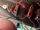
Hi everyone! Well I finally got around to installing the remote switch box. Overall it went fairly smoothly, what helped the most was having a wiring diagrams for my original lathe set up and the wiring diagram for the lathe with the remote switch. Vicmarc was great to deal with they answered all my emails quickly. I could have set it up so that the original start and stop switches on the front of the lathe remained working but that would have required me adding a terminal block and running a bit more wire. In the end it was worth me sourcing the terminal block. It was a bit tricky getting the wiring done so that the knee brake worked and the door that accesses the motor and step pulleys has a safety interlock on it so that the lathe won't start up if the door is open. I ended up not connecting it because that would have also required adding the terminal block. To get it all working I did need to completely remove the front of the lathe which also meant unbolting the inverter. Not really a big deal but not particularly easy for one person. The one thing that I learned and wish I knew at the beginning of all this is that the wiring for the switches on the front of lathe are attached to a terminal block (for lack of a better description). This block is easily unattached from the switch by a small little lever that is located on top of the block. The arrow in the picture is pointing at the black lever. Once the block is detached from the switch it is much easier to undo the screws to remove the wires.

IMG_5203.jpg
 
Hi everyone! Well I finally got around to installing the remote switch box. Overall it went fairly smoothly, what helped the most was having a wiring diagrams for my original lathe set up and the wiring diagram for the lathe with the remote switch. Vicmarc was great to deal with they answered all my emails quickly. I could have set it up so that the original start and stop switches on the front of the lathe remained working but that would have required me adding a terminal block and running a bit more wire. In the end it was worth me sourcing the terminal block. It was a bit tricky getting the wiring done so that the knee brake worked and the door that accesses the motor and step pulleys has a safety interlock on it so that the lathe won't start up if the door is open. I ended up not connecting it because that would have also required adding the terminal block. To get it all working I did need to completely remove the front of the lathe which also meant unbolting the inverter. Not really a big deal but not particularly easy for one person. The one thing that I learned and wish I knew at the beginning of all this is that the wiring for the switches on the front of lathe are attached to a terminal block (for lack of a better description). This block is easily unattached from the switch by a small little lever that is located on top of the block. The arrow in the picture is pointing at the black lever. Once the block is detached from the switch it is much easier to undo the screws to remove the wires.
Hi Scott,

I am new to the Vicmarc VL 300. I bought a 2004 VL 300 Short Bed with an upgraded 3 hp Leeson motor and an upgraded ABB ACS150 VFD. Both upgrades were done in 2014. The lathe appears to be in great shape. It is still sitting on a furniture dolly in my garage awaiting final placement. I would LOVE to add the remote switch box to permit me to move around the lathe if needed and for hollowing safety. Would it be too much of an imposition to try to work with you to figure this out for my new purchase? Thanks, Mike
 
Hi Scott,

I am finally ready to add the remote switch box to my 2004 VL300. It was sold by Craft Supplies so it has their version of legs and no emergency shutoff knee switch. I spoke with Craft Supplies at Marco’s suggestion. They were quite helpful. At their recommendation I am purchasing a 4” x 4” x 2.5” project box. They gave me some extension cable with an order I placed with them. My plan is to slide the lathe bed 12” toward the tailstock to access the front switches. I then plan to remove the ON; OFF; and SPEED CONTROL switches from the front and install them in my new project box. I plan to leave the POWER SWITCH and REVERSE SWITCH in their original location as I don’t need to access them often.

My plan is to simply solder in a cable splice between the original cable and the switch and the use heat shrink tubing to cover up the splice. From your experience do you see any issues with my approach? Would it be possible to send me the wiring diagrams or is it better for me to get them from Vicmarc or the Internet? Any other helpful thoughts? I could also give you a call to discuss if that is easier?

Thanks,
Mike
Consider keeping the emergency shutoff switch on the machine and wire a second cutoff button on the remote for safety. This way you’ll be able to reach whichever one is safest in an emergency. Shouldn’t be hard to figure out once you use a meter to see if the existing cutoff is either normally open or normally closed. Buy a second switch of the same type. If normally open then wire both cutoffs in parallel, but if normally closed then wire them in series.
 
Well, Vicmarc does have a magnetic box for controls, which is what my 240 has. Shouldn't be too much of a problem to hook it up. Not sure if Woodworker's Emporium could help you with that or not. I did find out that the variable speed knob turns the opposite direction as the ones on my other lathes do. Must be because they are on the other side of the equator....

robo hippy
change the wiring on the pot should do it
 
Consider keeping the emergency shutoff switch on the machine and wire a second cutoff button on the remote for safety. This way you’ll be able to reach whichever one is safest in an emergency. Shouldn’t be hard to figure out once you use a meter to see if the existing cutoff is either normally open or normally closed. Buy a second switch of the same type. If normally open then wire both cutoffs in parallel, but if normally closed then wire them in series.
Karl - Thanks for the insights and process. It makes sense. Because the newer VL300’s come only with the magnetic switch box my thought is to move it to the appropriate location before beginning to turn the piece. The lower left side of the original switches does not seem to be the optimal location. I think relocation the magnetic switch box to the upper left (kind of like the Powermatic) makes more sense while doing standard spindle work of rough turning. Then when I am hollowing I will move it slower to the tail stock end.
 
Hi Scott,

I am finally ready to add the remote switch box to my 2004 VL300. It was sold by Craft Supplies so it has their version of legs and no emergency shutoff knee switch. I spoke with Craft Supplies at Marco’s suggestion. They were quite helpful. At their recommendation I am purchasing a 4” x 4” x 2.5” project box. They gave me some extension cable with an order I placed with them. My plan is to slide the lathe bed 12” toward the tailstock to access the front switches. I then plan to remove the ON; OFF; and SPEED CONTROL switches from the front and install them in my new project box. I plan to leave the POWER SWITCH and REVERSE SWITCH in their original location as I don’t need to access them often.

My plan is to simply solder in a cable splice between the original cable and the switch and the use heat shrink tubing to cover up the splice. From your experience do you see any issues with my approach? Would it be possible to send me the wiring diagrams or is it better for me to get them from Vicmarc or the Internet? Any other helpful thoughts? I could also give you a call to discuss if that is easier?

Thanks,
Mike
Hi Mike,

Sorry but I can't find the wiring diagrams so it would be best if you contact Vicmarc. I emailed with them and they were always quick to respond. When I did added my switch box I left the old switches in the front of the lathe, but they no longer work, I also did not need to do any soldering. Once you have the wiring plan it should be come more straight forward for you. The one difficult part for me was that I had to remove the front panel on my lathe and slide out the inverter in order to access one of the power/project boxes. If you need to do it I strongly recommend having someone help you. Not sure if I can be of much more help as it was a few years ago and I really don't remember the details anymore.

Cheers,
Scott
 
Back
Top