• Beware of Counterfeit Woodturning Tools (click here for details)
  • Johnathan Silwones is starting a new AAW chapter, Southern Alleghenies Woodturners, in Johnstown, PA. (click here for details)
  • Congratulations to Paul May for "Checkerboard (ver 3.0)" being selected as Turning of the Week for March 25, 2024 (click here for details)
  • Welcome new registering member. Your username must be your real First and Last name (for example: John Doe). "Screen names" and "handles" are not allowed and your registration will be deleted if you don't use your real name. Also, do not use all caps nor all lower case.

Building a Rose Engine and looking for a bit of help

Joined
Aug 14, 2022
Messages
12
Likes
7
Location
Port Hope, ON
Hello all, I just recently joined Ornamental Turners International and noticed the forum has been moved over here. This will be my first post on either so please go easy on me if my forum etiquette is a bit off the mark. I only discovered the Rose Engine a short while back and I've been hooked since. I'm starting to work on a design for a build and I could really use some help. I mainly need a few rough dimensions so I can start doing a sketch or two. I do most of the design work on the fly as I fabricate and machine parts to suit despite all the drawbacks associated with working like that. I'd like a machine that will of course do ornamental wood turning but also be robust enough to experiment with guilloche as well as straight line work in metal. The natural choice is the Lindow Rose Engine, unfortunately buying a turn key machine wouldn't be in the budget until many years after the kids are through college. I don't want to wait 10-15years!
What I'd like to do is build the base machine and use Lindow Rosettes, rubbers, leveling chuck, straight line attachment, cutting frames etc. The list is endless and I can buy pieces as the budget allows. I know most of what I need to make the crossing plate, worm and barrel assembly do what it needs to do with the rocking frame and tower to hold the rubbers. I have no intention of copying the Lindow machine, mine will be much simplified, less precise and based off of materials I already have gathered in my steel rack.
What I am having trouble with is the scale of the machine, I always picture it being much larger that it really is. It would be very helpful to know the dimension from the lower pivot bushing center to center of the 1" main shaft. I'd like to keep that dimension as close to the Lindow as possible in the hopes I'll add the Lindow Hardinge lower mount and a rebuilt Hardinge crosss slide to the machine one day.
The other dimension I was looking for was the main shaft pulley diameter. I haven't worked out the rest of the pulleys yet, that can come latter though. I was also looking for the nominal bore size of the Lindow rosettes so I can get a general idea of the barrel diameter. I'll use the rosettes themselves for final fitting. It would also be helpful to know how much room the straight line attachment takes up when it's bolted to the front face of the "U" frame. The "U" frame will be machined from 3 peices (at least) of cold rolled flat bar stock bolted together, using keyways or dowels for locating. This is the hardest part of the build for me, getting the pieces machined and attached together while holding less than 0.001" clearance between the bronze bushings and 1" main shaft is going to be tricky.
I know I've missed a few things and I'm sure a few more questions will come up as I go. I'd really appreciate any help your able to give and welcome any and all input, good or bad. I know I've really rambled on here and I hope what I wrote makes sense. Thank you for taking the time to read this, I really hope this new forum location brings more like minded people together to share their knowledge!
 

RichColvin

Super Moderator
Staff member
OTI Member
Joined
Mar 13, 2016
Messages
667
Likes
497
Location
Marysville, OH
Website
www.colvintools.com
Jeff,

There are two online resources you might find useful:

Ornamental Turning Book of Knowledge (OrnamentalTurners.info). Loads of information you’ll probably find useful there.

MDF Rose Engine Lathe 2.0 Library (https://mdfre2.colvintools.com/) This is one I maintain, and it has a number of items there on the design of the MDF Rose Engine Lathe (check out the User manual on the 1st shelf, and the build manuals on the 2nd shelf). There will probably be lots of useful information you can use to help design your own machine.

But rather than engineering your own machine from the ground up, I recommend you building an MDF Rose Engine lathe. That is doable for a very reasonable cost, and you will learn lots for any future machines you may make.

Rich
 

RichColvin

Super Moderator
Staff member
OTI Member
Joined
Mar 13, 2016
Messages
667
Likes
497
Location
Marysville, OH
Website
www.colvintools.com
Jeff,

I should add: I built my first one using an old midi lathe as the headstock, mounting it atop pillow block bearings. You can see more about that at this link, including some videos of it in action. It worked, and enabled me to get into rose engine work. But what I found was that I didn't understand how much the weight of that headstock in the rocking movement made for a really unstable machine.

That machine was disassembled, and I built the original MDF Rose Engine Lathe. It was a significant difference in usability.

Having made a third machine now, I had a very different understanding of the engineering decisions for making such a machine.


One more thing: the Rose Engine News was a newsletter that was put out about 10-15 years ago for Lindow-White Rose Engine users. There is a lot of information there. One which may be of note is this one: Useful Lindow Rose Engine Facts and Constants, by Roy Lindley, with additions by David Lindow & Brian Clarry (https://lindowmachineworksdotcom.files.wordpress.com/2016/05/lindow-white-rose-engine-news-v5n2.pdf), starting on pg. 20.

Rich
 
Joined
Aug 14, 2022
Messages
12
Likes
7
Location
Port Hope, ON
Good day Rich,
I really appreciate the information. I'd come across links to building plans for the MDF lathe in the forums but they were all dead and I didn't follow up further. The work the MDF Rose Engine is capable of is simply amazing. I've been building machinery all my life and I would never have guessed a machine built from wood could cut cut so accurately or be robust enough to handle large projects like it does. Having the phasing holes in the rosette really simplifies things as well. The newest version with the synchronized drives can really take the machine to the next level, it will be interesting to see how far it goes. The build information should come in very, especially the drive.

I came across your midi lathe rose engine early in my searches, I seriously considered going down that road at first. I even had my mini lathe sitting up on top of another lathe for a few weeks while I considered it. Once I made the decision to build a rose engine I realized I wanted one as much for metal work as I did for wood hence the decision to build in metal. My metal working working skills far exceed my wood working capabilities as well though I'm looking to change that in the years ahead. I'm an industrial millwright by trade but spent over half of my career building custom machinery. I can understand why you'd recommend a more modest approach to ones first rose engine build and I'd have likely gone that route if soo much information wasn't available online these days. I considered a couple more modern approaches to building a rose engine, they were far easier builds and would have used rosettes with the indexing holes drilled in them like yours do and roller bearings instead of bronze. I even have a headstock I could have used that was left over from a machine I built years ago. I'm a sucker for antique machinery though and I decided my rose engine has to have just a little of that old world personality, even if it's early 20th century design.

It's not an easy build by any means but once I understood how the phasing plate works it became a less daunting project. I have the machinery to do it and all the steel to build the base machine. I'd prefer to be using cast iron for many of the parts but regular old steel will suffice with a bit of care. I may end up buying the main shaft, It would be nice to have to have an accurately ground surface to fit the headstock bushings, rosette barrel bushings and pulley to. The 2mt would be really nice for transferring work to my metal lathe and mini wood lathe. I have aluminum to make the worm wheel(s) from, if it doesn't stand up I can always make bronze one(s) down the road. It's OK if it's not perfect the first time around.

The facts and constants in the Lindow newsletter was extremely helpful,. I used cardboard to do a quick sca;e layout of the machine, I had to smile because the machine is soo much smaller that I keep picturing it in my head. I really appreciate you taking to the time to post that for me. It made me realize I'd seen a heading for a newsletter on the OTI website and I got lost reading them until 2:30am last night. I had missed a lot of the resources available to me as a member. The information they contain is pure gold and I'm looking forward to reading them all. Lots more to read on the Lindow site as well. I still need to find out the Rosette I.D. for the barrel but other than that I think I have all the key dimensions I need to start doing a few sketches. It will be at least a couple months before I really get going. I have a forging press to finish up and some tooling to make for it first. I was surprised there weren't more Rose engine builds posted online so I'm going try and post as much detail as possible here as I progress things. Hopefully someone else will find it useful.

Thankyou for reaching out Rich and spending the time to help me out. I really appreciate it. I'm a lot closer to making this happen than I was a couple days ago.
Take care,
Jeff
 

RichColvin

Super Moderator
Staff member
OTI Member
Joined
Mar 13, 2016
Messages
667
Likes
497
Location
Marysville, OH
Website
www.colvintools.com
Jeff,

The machine built by Jean-Claude Charpignon has a rocking headstock atop a lathe bed. It was re-built by Fred Armbruster as the Armbruster-Charpignon fixed tool machine. You can see a picture of it on Fred Armbruster's Instagram channel, or at the OT BoK (look at https://ornamentalturners.com/wiki/index.php?n=Main.CharpignonArmbrusterLathe). Do note though that these machines have significant pressure on the swing of the headstock, so the rosettes used there are usually made from steel.

But they are used to make (very beautiful) wood pieces.

If you are looking to make steel pieces, are you looking to ornament the end of a piece (e.g., Guilloché or Engine Turning), or cutting into the side of a piece? The cutting tools used for these are very different than used on wood. I know there is another fella looking at cutting on the side of metal. Not sure if he was going to use diamond bits or something else.

A different tool for ornamenting steel is certainly a laser.

Kind regards,
Rich
 
Joined
Aug 14, 2022
Messages
12
Likes
7
Location
Port Hope, ON
Hello Rich
The Armbruster-Charpignon is certainly a beautiful machine. I can understand why steel rosettes are used, the surface area of the cutter would be causing significantly higher forces than a spinning cutter on wood or the couple/few thousands of an inch removed in guilloche. You wouldn't be able to use a fixed tool like that on metal without a much larger machine. The Armbruster Rose Engine lathe is a work of art, both versions. One can dream of building something that beautiful one day. It must be something to design and build a world class machine that will still be cherished centuries from now. As far as the steel work goes I should have made it clear I was talking about guilloche, mainly. I also want to use eccentric cutting frames with nonferrous alloys. I'm curious to see how an endmill in an er collet spindle performs on copper/silver/bronzes and brass. I'd like to experiment with mokume gane to see if guilloche compliments it, I make the stuff and want to try new ways of using it.

I do want to do straight line engine work using a rack and pinion style attachment. The list gets long from there, leveling chuck, double eccentric chuck, dome chuck, cutting frames etc. Much of this I will buy over time and some I will make. I have a power hone and hand sharpening setup that I use for square/round gravers, I finish at 50000 grit. I've also got a home made setup for single lip cutters. With a couple modifications for tool size I'll be all set for the basic cutter shapes, Anything more complicated I'll buy from the professionals. I just came across a compound slide from an old pattern makers lathe that another OTI member is going to sell me, it looks to be very well make and a better deal than I though I'd ever find.

As far as cutting down the sides of metal goes, like putting a piece of round bar stock in a 3 jaw chuck similar to a standard metal lathe. Could you not do a series of guilloche style radial cuts using a pumping rosette? You'd probably need a lathe bed attachment and tailstock if it had any kind of length. Or are you talking about axial cutting along it's length? It's possible an end mill in drilling frame might work if your rocking the head. The endmill would be moving on and off of center as the metal work piece rocked in and out. It would have to be a rigid setup with very light passes and a cutter running at very high speed in a non ferrous alloy. If you could stop the cutter from breaking, then wandering the surface finish would likely be a big issue. Can you get 15000 plus rpm out of a er collet drilling frame? Or are you talking about something else? I'm speculating of course. A spring loaded diamond drag tip would cut to a point but it leaves a burr and I can't see it working well with phasing or overlapping cuts.

A laser would certainly be a nice tool to have, I know a couple guys who are getting incredible results, once the piece has been finished the average person would think it was hand engraved, You can go as deep as you want, it just takes a long time. The big problem for me is the learning curve involved with the design software, coming up with complex engraving patterns isn't easy either I imagine. I was given a deckel G1L pantograph last year, it should do a beautiful job and handle everything involved on the rose engine build.

I'm not delusional enough to think that I won't encounter issues while doing this build. I just hope I can overcome them all without too much rework. One thing I wish I had was a surface grinder. Thank you for sharing again, I've got a few new things to consider and they will be added to the growing list.

Take care,
Jeff
 
Joined
Aug 14, 2022
Messages
12
Likes
7
Location
Port Hope, ON
Thanks again Rich,
it's been awhile since I've been as excited about the machine build itself as I am about using it for it's intended purpose once it's done. This will
be the first machine I've built for myself where the learning curve to mastering it's use is more complicated than the build itself. Of course the build can get more
complex than it's use if you factor in geometric chucks and other attachments etc but that's far beyond the scope of my build. I'm not deep enough into it at this point
to know all the questions that I need to ask yet let alone knowing their answers, the hard part is yet to come!

This is to everyone.. A dedicated Build area where people can post pictures and share information about their rose engines and ornamental lathes might encourage
more people to start asking questions. I've come across so many people that expressed an interest in ornamental turning but were put off because there were more questions
than answers involved in getting started. With the move of the OTI forum to the much larger platform of the AAW I'm hoping we'll see a lot more discussion and sharing
of information in the coming year. I know it's it's a relatively small sub section of wood turning in general and the number of people using ornamental lathes and rose engines
isn't very large but it feels like the forum presence isn't keeping pace with the growing interest in OT.
It could be that I'm missing point altogether and that there's a reason why this isn't being done. I know I'm not the only one interested in building an OT lathe of some kind.
There was a vigorous discussion as to what should and what shouldn't be considered a rose engine or ornamental lathe. There's nothing wrong with including all types of OT
work here, whether they get divided into sections or all lumped together is less important than nobody posting anything at all. I'm hopeful we'll see a surge of interest on the
forum this year!
Kindest regards,
Jeff
 
Joined
Feb 23, 2023
Messages
7
Likes
2
Location
Kennewick, WA
Hello Jeff,

I took a similar path to the one you are contemplating. It has taken me a while but I am enjoying the building of the rose lathe machine. It is challenging and I make some mistakes because of the limited information available, but it is fun. The downside was that I am just now getting close to actually use it and expect there will be more discovery regarding tolerances and capabilities.

I am a bit reluctant to offer advice given my limited knowledge and experience with this. But with regard to your question on the pivot, I surmised that the longer the pivot arm the better the machine might work and placed the pivot well below the work top And leaving 8” clearance from work surface to spindle center. So I think perhaps that latter distance is the more critical. Not so much that you can turn large objects but that you can also make the cam-disks large enough that they work easily, and the index plates are perhaps easier to make too.


Greg
 
Joined
Aug 14, 2022
Messages
12
Likes
7
Location
Port Hope, ON
Hello Greg,
The 8" shaft center to work surface sounds just right. I've been digging up information from OTI newsletters, Instagram posts, forums and Facebook. From that I'd settled on 7" from main shaft centerline to the lower pivot centerline, leaving me close to 8" to the work surface.
I'd be very interested to see your rose engine lathe if your ready to show it. My favorite part of this process has been seeing other people's custom rose engine builds. I'll enjoy building my rose engine as much as I will using it when it's done. I don't think the build portion will ever end once started, the list of chucks, cutting frames and specialized accessories is endless.
I do plan on buying some of these to start, including the rosettes that David Lindow makes for his rose engine. The more complex items with bigger price tags I'll have to make over time. Hopefully I can find a balance between budget and building so I'm not stuck with an endless machine build that I never get to use.
I just bought an early 1970's Elite AR5-E universal tool and cutter grinder. It looks like a capable little machine and as a bonus it has enough travel for surface grinding pieces up to about 11 1/2" x 6". It needs a bit of TLC and I'm replacing the 550V motor with a variable speed 3/4 hp 90volt dc motor. It's part of a list of things that need to be done before or during the Rose engine build.
It's going to be a bit of a long term project getting this build done the way I want to. Using a cheap X/Y table is one way I'll get it up and running faster. It will be replaced over time with a more period correct looking one with a lot more features.
I can't decide on the material size for the "U" shape headstock. Part of that is not fully understanding how the rose engine weight distribution should work. Most of the examples out there have a wider, heavier cross section at the main shaft centerline. Then there's the considerable weight of the pulley, phasing wheel, worm gear plus the barrel assembly and bronze rosettes. I'm wondering if you (or anyone else) knows if the added weight there helps make the machine run more smoothly. I've got 1" x 2 1/2" steel barstock or 2" x 3 1/2" steel barstock to make the "U" shape headstock from.
If added weight on the mainshaft centerline is desireable the heavier material may be a better choice. I could keep it full width for 4" or so at the main shaft centerline and thin out the lower sides and bottom to 2 1/2" wide or so.
I'd sooner build too heavy than too light so it's rigid for doing metal work. It would be nice to know why it should or shouldn't be done rather than just copying the build style of existing rose engine latnes.
What were the main challenges you faced during your build Greg? Did you run into any tolerance issues with the finished build? I know I've been adjusting my thoughts on the build/machining approach as I go so tolerance buildup from part to part doesn't become an issue in the finished headstock.
Any issues with getting the headstock dialed in to your x/y table? How close were you able to get it before introducing a leveling chuck? What rosette "bump counts" did you include on your phasing wheel/plate? My apologies if the terminology isn't correct.
Are you building a straight line attachment for your?
I suppose that's plenty of questions for now and I realize you may not have all the answers (yet!). Anything you can share would be very helpful. If you've built a rose engine then you have the experience to offer advice as far as I'm concerned! You could save me from making a costly, time consuming mistake. I hope your rose engine is a great success Thank you for your input.
 
Joined
Feb 23, 2023
Messages
7
Likes
2
Location
Kennewick, WA
Hi Jeff,

Maybe someone can let us know if we should take this offline. Like I said, I am doing this kind of like you are because I am enjoying the project and it is all for my own entertainment. Here are a couple pictures of where I am at so far;

1677372875840.jpeg

1677373075550.jpeg
 
Joined
Feb 23, 2023
Messages
7
Likes
2
Location
Kennewick, WA
Jeff,

More detail on some of your questions. I also thought heavier to some extent might dampen vibrations and improve things. So mine is heavy as you can see. It appears this is okay as the pivot only rocks a small distance from center and the weight doesn’t seem to create a problem as far as I can see. Again, I have only cut a couple of test pieces so far. The rosettes are well defined in some of the ornamental turning literature and there are almost infinite shapes. It looks like one could be pretty entertained by about six basic shapes because of all the combinations possible. The bigger issue I have had is to understand the right amplitude for sizes I will cut. I think I made most of mine so far with too much amplitude, will see. I made mine using Aspire software and a CNC router and they are hdpe and they seem okay. Also made some pumping rosette’s but haven’t tried that yet. I have more hdpe so expect to make more rosette’s after trying the lathe out.

I bought the spindle as I have made a spindle before and found it difficult to get everything as nice as I wanted. Things I had difficulty with included cutting the groove in the round belt pulley’s and indexing disk, boring the u-frame for the pivot bar and for the spindle. The spindle is still tighter than I would like, but I think it is okay for rocking. Next week I am going to make some springs and will see if it moves freely enough for pumping movement. Making Some pieces like the worm gear for phasing and the phasing lever that operates in the phasing slots was a challenge because they were small and challenged my filing skills (pretty low bar there). Making cutters is a challenge for some of the same reasons.

I had an old hardinge lathe compound that I cleaned up and adapted for managing the cutters. I have used some mag locks for holding the compound and have a smooth table. Will have to see how that works out as well, but initial work on test spools it seemed okay.

Greg
 
Joined
Sep 2, 2013
Messages
25
Likes
74
Location
Barrhead, Alberta, Canada
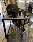
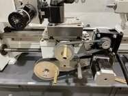
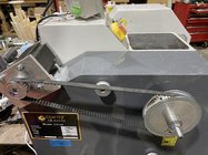
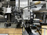
Hi all. I worked backwards from Bill Ooms’ COrnlathe software to a hardware solution. COrnLathe has pretty much everything a fellow needs for designing OT projects, experimenting with rosettes, cutters, etc. The software will create the GCode needed to run a simple 3 axis CNC lathe. With that in mind I have adapted a small 10“ x 22” metal lathe for ornamental turning. It has XZ linear axes, and a C rotary axis.

It is all coordinated with a very inexpensive Mach3 USB motion control card. I do realize much of the fun of Ornamental Turning is the hands on, but for me the fun is easily creating embellished items after designing them in software. All I needed was three Nema23 stepper motors plus drivers, 6 pulleys and belts, a mounting bracket for two of the steppers and a mandrel for the rotary stepper. An inexpensive 800w variable speed dc spindle can be run either horizontally or vertically with simple tool post mounts. I made a couple simple fly cutters for using 1/8” carbide router bits. I can quickly regrind the bit profiles as needed with a simple platform jig and a 4” diamond cup wheel mounted on the lathe. I haven’t needed to build cutter frames yet but that is likely later for deep work.

On GitHub, COrnLathe is available for Macs, or more practically now for Windows (search COrnlathe for Windows). This is a free program thanks to Bill Ooms’ generosity. It can be run just as a design program too to aid working out pattern ideas.

I can still also use my machine as a manual metal lathe as well. This is helpful for making new tools.
Unmounting the modifications takes about 5 minutes.

Cheers, Jeff H.
 

Attachments

  • 5EFACE19-9407-4125-9D26-FFBA16F16781.jpeg
    5EFACE19-9407-4125-9D26-FFBA16F16781.jpeg
    460 KB · Views: 47
  • C85951E8-5200-4E22-B9DB-1A79FD6CEF91.jpeg
    C85951E8-5200-4E22-B9DB-1A79FD6CEF91.jpeg
    478 KB · Views: 45
  • C6008BB4-9ADA-4FCB-8FAC-4B01C2A9CDAE.jpeg
    C6008BB4-9ADA-4FCB-8FAC-4B01C2A9CDAE.jpeg
    489.5 KB · Views: 45
Joined
Feb 23, 2023
Messages
7
Likes
2
Location
Kennewick, WA
Wow, that is a really elegant lathe conversion. I converted an Atlas Craftsman, but my conversion was more complex and I think probably harder to use than what you shared. Enjoyed your photo’s and description.

Greg
 
Joined
Sep 2, 2013
Messages
25
Likes
74
Location
Barrhead, Alberta, Canada
There is a lot of backlash in the lathe as it comes from the factory. This is typical of these little lathes I think but fortunately Mach3 and the Grbl version I use can account for the backlash and provide a decent result I think. To get rid of it I would have to change to ball screws and thereby lose my power feed for the carriage and cross slide. Since I still need to learn how to use a metal lathe I won’t bother with that change.
Cheers, Jeff H.
 
Joined
Nov 28, 2023
Messages
43
Likes
23
Location
Royal Oak, MI
Hello all, I just recently joined Ornamental Turners International and noticed the forum has been moved over here. This will be my first post on either so please go easy on me if my forum etiquette is a bit off the mark. I only discovered the Rose Engine a short while back and I've been hooked since. I'm starting to work on a design for a build and I could really use some help. I mainly need a few rough dimensions so I can start doing a sketch or two. I do most of the design work on the fly as I fabricate and machine parts to suit despite all the drawbacks associated with working like that. I'd like a machine that will of course do ornamental wood turning but also be robust enough to experiment with guilloche as well as straight line work in metal. The natural choice is the Lindow Rose Engine, unfortunately buying a turn key machine wouldn't be in the budget until many years after the kids are through college. I don't want to wait 10-15years!
What I'd like to do is build the base machine and use Lindow Rosettes, rubbers, leveling chuck, straight line attachment, cutting frames etc. The list is endless and I can buy pieces as the budget allows. I know most of what I need to make the crossing plate, worm and barrel assembly do what it needs to do with the rocking frame and tower to hold the rubbers. I have no intention of copying the Lindow machine, mine will be much simplified, less precise and based off of materials I already have gathered in my steel rack.
What I am having trouble with is the scale of the machine, I always picture it being much larger that it really is. It would be very helpful to know the dimension from the lower pivot bushing center to center of the 1" main shaft. I'd like to keep that dimension as close to the Lindow as possible in the hopes I'll add the Lindow Hardinge lower mount and a rebuilt Hardinge crosss slide to the machine one day.
The other dimension I was looking for was the main shaft pulley diameter. I haven't worked out the rest of the pulleys yet, that can come latter though. I was also looking for the nominal bore size of the Lindow rosettes so I can get a general idea of the barrel diameter. I'll use the rosettes themselves for final fitting. It would also be helpful to know how much room the straight line attachment takes up when it's bolted to the front face of the "U" frame. The "U" frame will be machined from 3 peices (at least) of cold rolled flat bar stock bolted together, using keyways or dowels for locating. This is the hardest part of the build for me, getting the pieces machined and attached together while holding less than 0.001" clearance between the bronze bushings and 1" main shaft is going to be tricky.
I know I've missed a few things and I'm sure a few more questions will come up as I go. I'd really appreciate any help your able to give and welcome any and all input, good or bad. I know I've really rambled on here and I hope what I wrote makes sense. Thank you for taking the time to read this, I really hope this new forum location brings more like minded people together to share their knowledge!
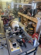
Hello. I've been thinking on these lines as well for a while.
ONE Suggestion.

1768 Style Potters Lathe Designed by Wedgwood​

View: https://www.youtube.com/watch?v=n-7twF5_chU&t=201s


This pottery lathe is both simple and elegant in my way of looking at it. One rosette vs many on the barrel, On the end for easy change over, Pumping movement...
This is a lot to like with this lathe. Keep I simple stupid (K.I.S.S.) principle is always best for me.
Wish you luck on your venture. Cant wait to see what you make/fine/ or buy.
Good luck.
C.A.G.
 
Joined
Nov 28, 2023
Messages
43
Likes
23
Location
Royal Oak, MI
Hi Jeff,

Maybe someone can let us know if we should take this offline. Like I said, I am doing this kind of like you are because I am enjoying the project and it is all for my own entertainment. Here are a couple pictures of where I am at so far;

View attachment 50503

View attachment 50504
Hello Greg.
ONE question on my Rose lathe. the LONG pivot from the main shaft to your bearing? dose having a longer pivot point help, I like your machine, but your scale is different form what I've seen else ware. can you explain what you did and why?
Thank you .

C.A.G.
 

RichColvin

Super Moderator
Staff member
OTI Member
Joined
Mar 13, 2016
Messages
667
Likes
497
Location
Marysville, OH
Website
www.colvintools.com
Curt,

yes, a longer pivot on the headstock does work better.
 
Back
Top