• Beware of Counterfeit Woodturning Tools (click here for details)
  • Johnathan Silwones is starting a new AAW chapter, Southern Alleghenies Woodturners, in Johnstown, PA. (click here for details)
  • Congratulations to Keven Jesequel for "Big Leaf Maple" being selected as Turning of the Week for April 15, 2024 (click here for details)
  • Welcome new registering member. Your username must be your real First and Last name (for example: John Doe). "Screen names" and "handles" are not allowed and your registration will be deleted if you don't use your real name. Also, do not use all caps nor all lower case.

Cutting a hemisphere on the end of your OT turning...

Joined
Dec 5, 2015
Messages
749
Likes
363
Location
Seattle, WA
This may be the forum's first posting of an OT technique...

This is a way to make the end of your work piece hemispherical. The work is rotating slowly, but not rocking by a rosette. The cutter would be rotated at high speed by an overhead drive belt like used for cutting frames. The cutter is fed slowly into the work using your machine's cross slide tool holder.

The angle A of the rotating cutter with respect to the lathe spindle axis is :

arcsin of c/R, where "c" is the cutter radius and R is the desired workpiece radius.

This is something that's done on milling machines to make accurate hemispheres with the cutter tip positioned exactly over the center point of the hemisphere location. That works well on homogeneous materials. But for wood with grain the cutter has to be positioned slightly off center so it only cuts with the grain. Looking down on my crude diagram that would mean the cutter has to be slightly below (or above) the work's center of rotation depending which way the cutter is rotating.hemi cutter.JPG
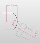
BTW: I did the calculation from memory so if it's wrong let me know.
 
Last edited:
Joined
Dec 5, 2015
Messages
749
Likes
363
Location
Seattle, WA
This is a well used, old technique for cutting convex and concave hemispheres in machine shops. Where there is no CNC, no lathe available or the part doesn't lend itself to lathe mounting this is a good method. A simple setup most shops already have like a Bridgeport type mill and a rotary table can do high accuracy work.

I suppose it could be called an eccentric cutting frame. Rich in his BOK (which I wasn't aware of until this thread) has a link to eccentric cutting frames. The linked JaHo video shows an example of an eccentric frame setup, but that one looks expensive and won't do this cut because the work holding axis doesn't rotate, it only indexes . The hemisphere could also be done with a ball turning attachment.

I've been away from OT for quite awhile. My first exposure to OT was the Seattle symposium 15 or so years ago. At the symposium I felt a bit like being surrounded by a lynch mob when I said my instant gallery pieces were CNC'd. Now I see a gradual creep toward CNC with stepper motors, etc. Still there's opposition to CNC.

I've always thought Bill Ooms OT work was world class. Far and above most OT work I've seen that was done using the old OT techniques. Now I follow BOK links and find Bill's work was done with CNC using linuxcnc. Never a mention of CNC in his journal articles.

If the intention is to do OT type work on a budget then my advice is buy a CNC router from Woodcraft or Rockler. Maybe add a rotary axis as you get comfortable with CNC. You're good to go at a fraction of the cost of assembling the parts to build your own traditional OT type machine. No matter how the work is done, the design is still the most important part of the process and that applies to CNC or traditional OT.
 

RichColvin

Super Moderator
Staff member
OTI Member
Joined
Mar 13, 2016
Messages
668
Likes
500
Location
Marysville, OH
Website
www.colvintools.com
Alas, I must report that Bill Ooms is no longer doing ornamental turning. Jon Magill now has his COrn Lathe.
 
Joined
Dec 5, 2015
Messages
749
Likes
363
Location
Seattle, WA
Somehow I was aware Bill Ooms was not doing OT anymore.

But, Jon buys his lathe, that's a surprise. 15 years ago I was telling him he should buy CNC.
 
Last edited:

Jon

Joined
Feb 28, 2007
Messages
18
Likes
16
Location
Shady Cove, OR
Website
www.rogueturner.com
Now Doug... I just tried to explain the "Dark Side" comment in the other thread here. It was intended in a complimentary way, and in jest. What you were doing back then was w-a-y ahead of the time, and only a few other people were even dabbling in the complex stuff you were playing with back then.

I have multiple CNC "things" now, and a lot more experience with some of the newer software out there, especially the more "artistic" applications, like Vectric's Aspire. When people ask about software I now try to explain why I use some software for more "mechanical CAD" and other for "more artistic design". The two couldn't be more different in their workflow and tools for modifying and editing shapes.

As Rich mentioned above, your example is what we call an eccentric cutting frame, or ECF, and it can cut many more shapes than just a perfect hemisphere. I show an example of a more "acorn like" shape being cut on the third page of this article if you want to see one in action.

--Jon
 

Jon

Joined
Feb 28, 2007
Messages
18
Likes
16
Location
Shady Cove, OR
Website
www.rogueturner.com
I had to stare at this a while, but it appears that the "length" of the curve would be limited by "c".
Pretty much... 'c' and the length of the cutting tip. Most ECFs let you change how much the cutting tip projects out of them, allowing the body of the tool to not smack into the workpiece.

My eccentric cutting heads, with a shank that goes into a drill spindle, have interchangeable "bars" of various lengths, to allow cutting larger or smaller "domes".

--Jon
 
Joined
Oct 24, 2016
Messages
3
Likes
3
The attached article may be useful if you wish to calculate precise values for your cutting frame setting for a given size dome. It was in volume 28, No. 1 of the OTI Newsletter published in May, 2021.

Frank
 

Attachments

  • Cuting Domes.pdf
    1,004.1 KB · Views: 17
Joined
Jul 19, 2018
Messages
1,710
Likes
2,243
Location
Ponsford, MN
The attached article may be useful if you wish to calculate precise values for your cutting frame setting for a given size dome. It was in volume 28, No. 1 of the OTI Newsletter published in May, 2021.

Frank
A while back I had an idea to to cut a narrow band to go on a tapered lamp shade that was turned to about 1MM thick. The math was explained as calculating a truncated arc such that all you needed to do was enter the diameter as the length of the the arc and the rise and it would calculate the necessary radius or if you didn't trust their calculation they also gave the formula. There is another similar one for calculating a truncated cone for sheet metal layout, which is the one I used to make my band.
IMG_20200608_142405.jpg
 
Back
Top