• May 2025 Turning Challenge: Long Neck Hollowform! (click here for details)
  • Congratulations to Phil Hamel winner of the April 2025 Turning Challenge (click here for details)
  • Congratulations to Dion Wisniewski for "Basketweave" being selected as Turning of the Week for 12 May, 2025 (click here for details)
  • Welcome new registering member. Your username must be your real First and Last name (for example: John Doe). "Screen names" and "handles" are not allowed and your registration will be deleted if you don't use your real name. Also, do not use all caps nor all lower case.

general 26020 VD wiring

Joined
Oct 12, 2021
Messages
8
Likes
4
Location
Fort Myers, Fl.
Good Morning , Happy 4th!
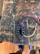
Just purchased a new to me General 26020VD lathe. I had to disassemble it to move and photo'd the wiring for switches and drive. BUT, I am left with one black wire coming from start/stop switch and cannot determine it's location.
I have the Altivar 28 manual but it doesn't show anything about the General machines wiring.
the General literature also does not show the wiring
The start/stop switch runs thru a relay before switching the drive
Do any other General owners have a schematic ?

Thanks, and Thank you Veterans for your Service and Sacrifice.


IMG_1564.jpeg
 

Attachments

  • IMG_1672.jpeg
    IMG_1672.jpeg
    646.6 KB · Views: 32
There are several videos on YouTube that walk you through the typical wiring of a VFD with a speed switch & start stop buttons.
Several of the videos draw out the schematic on a whiteboard, this might help you with the extra wire.
 
The way the wires are connected to the back of the start/stop switch looks like a classic pushbutton failsafe circuit. The contact block on the left is probably a normally closed contact operated by the stop button and the contact block on the right is probably a normally open contact operated by the start button. The white & red wires likely connect a normally open relay contact in parallel with the start button and the red wire also connects to the relay coil. The black wire is likely the power for the relay circuit and that voltage is most likely stated on the relay but the photo is upside down and blurred so I could not read it.
 
thanks for the response. I did work it out over the weekend and you are right Don. The black wire in question was the switched leg of the relay coil.
I do have another question though.
"General" wires the drive directly from the 220v outlet with no disconnect.
the circuit for the relay and run/stop switch piggybacks off the 220v supply only to interrupt the 24 volt supply to the f/r sw and speed pot.
Why use 220 volt to break a 24 v circuit when a simple toggle switch would do?
Thanks again.
The cord for the 220 VAC power has a plug on it and that constitutes a disconnect.
The speed controller probably has a built in 24 volt control circuit for the forward /reverse switch and the potentiometer but it does not have a failsafe start stop circuit, which the relay provides, so if you didn't have the relay then on a power failure & when the power was reestablished the motor would start up - not a good situation.
 
Back
Top