• Beware of Counterfeit Woodturning Tools (click here for details)
  • Johnathan Silwones is starting a new AAW chapter, Southern Alleghenies Woodturners, in Johnstown, PA. (click here for details)
  • Congratulations to Tom Hale & Rebecca DeGroot for "Walking Mushroom" being selected as Turning of the Week for September 30, 2024 (click here for details)
  • Congratulations to 2024 AAW Member Exhibition Common Roots forum member finalists (click here for details)
  • Welcome new registering member. Your username must be your real First and Last name (for example: John Doe). "Screen names" and "handles" are not allowed and your registration will be deleted if you don't use your real name. Also, do not use all caps nor all lower case.

Indexing on an Oval ?

Joined
Nov 28, 2023
Messages
51
Likes
25
Location
Royal Oak, MI
Hello.
Can anyone explain to me how to properly index an oval. I would like to make an Ornamental oval box.
The Oval box, Im pretty sure I can make, but how do you index something that is not round?
I saw Foster Geismann's video back on the early 2000's. but sadly he passed away.
Here is his video
View: https://www.youtube.com/watch?v=X4c_yFmaHso&t=6s

Making boxes and platters LIKE what he shows, is what I would like to do. But I can not find a lot of INFO. on his topic.

Thank you.

C.A.G.
 
Joined
Dec 5, 2015
Messages
824
Likes
409
Location
Seattle, WA
I can't say for sure how he did the indexing. Listening to him it seemed like he mentioned 72 divisions several times. That indicates to me he may have had a 72 position elliptical index wheel.

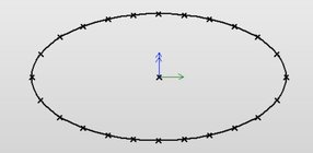
In CAD I made a 24 position elliptical index ring. Nothing special about 24 position indexing, it could as easily have been 17 positions or 99.

First I drew an ellipse 4 units wide and 2 units high. It could have been any combination of width to height. Then I divided the ellipse into 24 equal length segments. In this case each segment had a length of .4037 units. At the end of each segment I drew a point. It would be a simple operation to print my ellipse from the CAD screen and use that as a paper pattern to create an elliptical index ring. In my case I would make it on my CNC, but without CNC it could just as well be made manually.

The picture shows a screenshot of my CAD program.

24 segment ellipse.JPG
 
Joined
Dec 5, 2015
Messages
824
Likes
409
Location
Seattle, WA
I didn't mention another way to divide an ellipse. Rather than divide into equal length segments the ellipse can be divided into 24 angular segments of 15 degrees each which makes adjacent segments different lengths. That gives a different look with the segment lengths varying around the ellipse. I've tried both division methods in making oval type box lids. I recall liking the angular division method better.
 
Joined
Dec 5, 2015
Messages
824
Likes
409
Location
Seattle, WA
Finding sample pictures of the two methods of indexing ellipses mentioned above may not be so easy. I don't do a good job of documenting my work with photos. The photo below is an example of indexing a square with equal length segments (as opposed to equal angular segments).

In this case 48 equal length segments, 12 segments to each side of the square. Each of those segments are created with a cutter moving in an arc path. There are six different cutter paths (arcs) involved here. Each flute is an arc cutter path starting at the same position, ending at the same position and having the same position mid-arc, but different lengths. In CAD these would simple 3 point arcs. 6 distinct arcs each with a different radius. This is more of an exercise in CAD layout and then cutting on the CNC. I can't quite visualize how to do this on an OT lathe, there is probably a way though.

fluted square bowl-SharpenAI-Motion.JPG
 
Joined
Dec 5, 2015
Messages
824
Likes
409
Location
Seattle, WA
Here's poor quality picture of a 4 by 3 unit ellipse with an angular division of 20 degrees (18 segments). The flute width differs between adjacent segments. The tool orientation to the workpiece can have a major effect on appearance.

OT equal angle division.JPG
 

RichColvin

Super Moderator
Staff member
OTI Member
Joined
Mar 13, 2016
Messages
683
Likes
571
Location
Marysville, OH
Website
www.colvintools.com
Jon Magill figured this out for the bumpy ellipse rosette for the MDF Rose Engine. Here’s a paper chuck image drawn using it. Each bump is the same length, but the angles between them is changing as one progresses around the ellipse.

Rosette%20Paper%20Chuck%20-%20Bumpy%20Ellipse%20Near%20Side.png
 
Joined
Nov 28, 2023
Messages
51
Likes
25
Location
Royal Oak, MI
Hello Everyone.
sorry for the late reply's, I am just starting to understand how this forum work, (Its NOT user friendly!)

Any How , I made my own Oval jig.
View: https://www.youtube.com/watch?v=fR8ZwCHfv6Q
(on you tube.) I am trying to
figure all the possibility's to my new "Toy" Learning how to index an Oval is something That I would very much like to understand.

Thank you all for your reply's.
If you have any ideas or suggestions. Please note them.
thank you.

C.A.G.
 
Joined
Dec 5, 2015
Messages
824
Likes
409
Location
Seattle, WA
Curt, that's a nice setup.

You want to "index"? Do you mean break the oval into equal length segments. Or equal angular segments? There's quite difference.

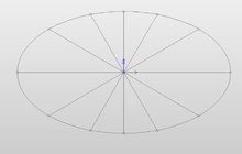
Here's an oval divided into equal length segments.

Oval equal length segments..JPG


Here's an oval divided into equal angular segments.oval angular segments.JPG

The equal angular segments are easy. Determine how many revolutions of the crank make a complete oval. For instance, if one turn of the crank made an oval then 30 degrees of the crank rotation would divide the oval into 12 sections.

I don't see an easy way to divide into equal lengths segments.

Another thing... sometimes what you are cutting is called an ellipse and sometimes an oval. With the type mechanism you're using you're creating ovals. Ellipses need a bit more complicated method to create. I believe the Vicmark makes ovals, not ellipses (but I'm not totally sure of that).

My design to make ovals is similar to yours. These designs won't by very good for turning because they aren't balanced for the rpm's needed for turning.
 
Joined
Nov 28, 2023
Messages
51
Likes
25
Location
Royal Oak, MI
Curt, that's a nice setup.

You want to "index"? Do you mean break the oval into equal length segments. Or equal angular segments? There's quite difference.

Here's an oval divided into equal length segments.

View attachment 59794


Here's an oval divided into equal angular segments.View attachment 59795

The equal angular segments are easy. Determine how many revolutions of the crank make a complete oval. For instance, if one turn of the crank made an oval then 30 degrees of the crank rotation would divide the oval into 12 sections.

I don't see an easy way to divide into equal lengths segments.

Another thing... sometimes what you are cutting is called an ellipse and sometimes an oval. With the type mechanism you're using you're creating ovals. Ellipses need a bit more complicated method to create. I believe the Vicmark makes ovals, not ellipses (but I'm not totally sure of that).

My design to make ovals is similar to yours. These designs won't by very good for turning because they aren't balanced for the rpm's needed for turning.
Hello and Thank you for the notes. I honestly did not think there was a difference form an Ellipse and an Oval.
I think equal length segments is what I want? The Goal is to add Ornamental details on my Oval work, things like basket weave and flutes... Uniformity is what I need. To make it look nice.
I believe that if I use an round index plate the indexes will not look uniformed to an Oval. Now indexing with the gear/cranks per rev. sounds like a better way for me to index.
This is a hole new adventure for me. I like to find out as much on a topic that I can. (I like the quote. "Only a fool, Thinks he knows everything." ) And I try not to play the fool as much as I can.

Thank you .

Have a good day.

C.A.G.
 
Joined
Oct 24, 2016
Messages
3
Likes
3
I seem to recall it was John Edwards who suggested a simple method for equal division of the ellipse. The technique was to cut a strip of paper a bit longer than the circumference of the ellipse, wrap it around the ellipse and mark where the two ends overlap. Cut the strip on the mark so it's the exact length of the circumference of the ellipse, lay it out on a flat surface and divide the strip into a number of equal increments that match the number of divisions you want. If you know how to use simple dividers, you can make quick work of this by stepping off an initial estimated increment, then adjusting the dividers until you are stepping off the exact increment for the number of divisions you want. Typically this takes surprisingly few passes to get the dividers set to the exact increment. Mark the increments with a pencil, wrap the marked strip back around your ellipse, and stick it on temporarily. Index from the pencil marks on the strip or transfer the pencil marks to the work piece, whichever is more convenient for the job, then proceed to make the desired number of decorative cuts.
 
Joined
Nov 28, 2023
Messages
51
Likes
25
Location
Royal Oak, MI
I seem to recall it was John Edwards who suggested a simple method for equal division of the ellipse. The technique was to cut a strip of paper a bit longer than the circumference of the ellipse, wrap it around the ellipse and mark where the two ends overlap. Cut the strip on the mark so it's the exact length of the circumference of the ellipse, lay it out on a flat surface and divide the strip into a number of equal increments that match the number of divisions you want. If you know how to use simple dividers, you can make quick work of this by stepping off an initial estimated increment, then adjusting the dividers until you are stepping off the exact increment for the number of divisions you want. Typically this takes surprisingly few passes to get the dividers set to the exact increment. Mark the increments with a pencil, wrap the marked strip back around your ellipse, and stick it on temporarily. Index from the pencil marks on the strip or transfer the pencil marks to the work piece, whichever is more convenient for the job, then proceed to make the desired number of decorative cuts.
Thank you Frank. the simple approach is always the best. Perhaps I was just over thinking the problem. ;-)

C.A.G.
 
Joined
Dec 5, 2015
Messages
824
Likes
409
Location
Seattle, WA
Not sure this qualifies as easy, but here's a description of the calculations to divide an ellipse into angles with an equal circumference including an example python program
Ellipses ae a special case of oval so fairly easy. Curt's setup makes ovals.

I assume Curt doesn't have CAD. With CAD it's a matter of graphically laying out the oval based on the mechanism of his machine. Once the oval is on the screen most CAD systems will divide it simply by using a "divide" command. That will also give the angular orientation of each segment in addition to its length.

My oval machine design has a crank arm that rotates to create the eccentric circle (oval). That's the way I can visualize the ovals to be cut. By laying out points on the oval at crank rotation of 0 degrees, 22-1/2 , 45, 67.5 and 90 degrees these points could be used to draw a curve through them giving (a nearly) exact shape of the oval. Then breaking that into equal segments with the "divide" command.

The method Frank mentioned could be done by wrapping the paper around the oval. to find the circumference then just divide the circumference by the number of segment lengths. This method doesn't have the elegance of the angular orientation of each segment which is a nice feature of Curt's machine with the hand crank rotation.
 
Joined
Nov 28, 2023
Messages
51
Likes
25
Location
Royal Oak, MI
Hello Everyone.
Doug by the word CAD do you mean "Carboard assisted" ? ;-p

I think my hand crank rotation will be the answer for me. my tables gearing/teeth should be a easy method of indexing my cuts?
Still untested at this moment. "Life" keeps getting in the way of all my wants. :) If all goes well between laundry and the weather TEMP. I hope to get some time in the shop this weekend? (NOTE I work Saturdays, So my weekend is Sun.-Mon. NOT Sat-Sun. Like the rest of the world. ) So there is still hope. ;-) Take care everyone.

C.A.G.
 
Joined
Dec 5, 2015
Messages
824
Likes
409
Location
Seattle, WA
Equal crank rev’s won’t result in equivalent circumferential segments.
Yes, you're right. Each equal length segment will have a different angular increment.

The way my design works I plot the upper right quadrant of the oval in CAD based on the crank arm setting of my jig. For16 equal length segments divide that quadrant into 4 equal segments using the "divide command". Then draw lines from the oval's center to intersect the oval contour at the end of each segment. For one of my 16 segment ovals first point of intersection was at 0 degrees rotation, then 18.4, 37.9, 61.5 and finally 90 degrees. From those numbers the other quadrant angles are easily figured.

Takes a bit more work for odd numbers of segments like 17 where the quadrants aren't horizontal/vertical mirror images.
 
Back
Top