I would like a closet to reduce noise.
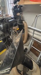
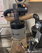
CLOSET I've posted all this before so sorry if you've already seen it. Or maybe someone else would be interested. When I built my shop I put in a 4x8' sound insulated closet. It holds the tall ClearVue cyclone and the 5hp 60gal air compressor (not as deafening as the ClearVue screamer but still loud!) When in use, I can still talk to someone in a whisper right outside the closet.
The closet is sound insulated above the ceiling and all the way around except for a double door that opens into a back room - I did use insulated steel doors there but the sound back there doesn't matter. The double doors are a big help when emptying the bin.
I used the "staggered stud" method of insulation: 2x6 wall but with 2x4 studs, one on the outside wall, the next on the inside wall, with insulation woven between them. (Eliminates direct sound conduction through the studs.) I read this method was sometimes used in sound studios.
Maybe a bit hard to see the design with all the shadows:

I ran the main 6" duct angled upwards to go through the ceiling, gentle bends, then long straight sections in the trusses, all hidden above the ceiling. Since the long horizontal ducts are all above the ceiling, inspection and cleanout caps are at the ends of the lines. The airflow is so strong I haven't seen or ever expect to see anything accumulating in the ducts.
Built a wide baffled plywood duct between the roof trusses to return the filtered air to the shop, coated with rubber spray on the inside and several turns to minimize sound reflections. My sketch for the air return duct:

A sub-panel and all the wiring is in boxes inside the closet with remote control of the DC anywhere in the shop and a motor disconnect for the air compressor on the wall outside the closet.
I did one thing for the air compressor that I'm really happy with - I ran the air line through the wall and put all valves and things out in the main shop instead of inside the closet - water separator, desiccant dryer, regulator, and valves to distribution lines installed in the walls. One big advantage of building everything myself was it ended up exactly like I wanted it! The disadvantage was if the dumb builder messed up I could only blame myself...

Floor plan showing closet location. (the maintenance bays are now 1/2 full of dry and drying turning blanks on wire shelves. Couldn't get a vehicle in there if I had to)

JKJ


 mullettools.com
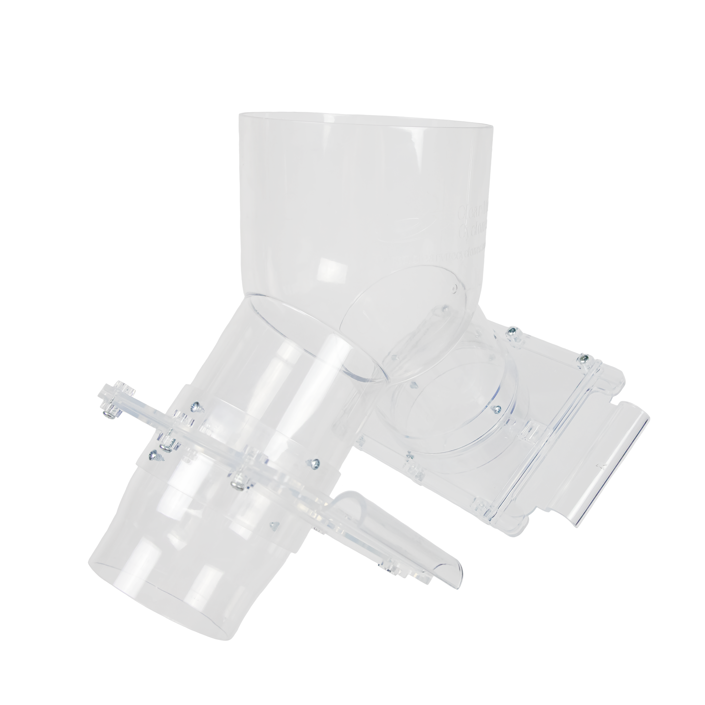
") Even restricting the area to 1/2 much reduces the dust pickup at the lathe, all else equal. I’d have to review some principles but I suspect in both significant turbulence and friction in the compressible fluid (air) flow may need to be considered. Might be much different if guillotine blast gates and the ClearVue 6” to dual 4” splitter box had been designed to smoothly reduce the restriction area to something more like I remember seeing in the ideal diagrams in the books.
Even restricting the area to 1/2 much reduces the dust pickup at the lathe, all else equal. I’d have to review some principles but I suspect in both significant turbulence and friction in the compressible fluid (air) flow may need to be considered. Might be much different if guillotine blast gates and the ClearVue 6” to dual 4” splitter box had been designed to smoothly reduce the restriction area to something more like I remember seeing in the ideal diagrams in the books.


 There's a 6-inch port and blast gate sitting idle behind the lathe until I finally sort all that out.