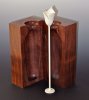
I have an idea for a hollow form that I've been trying to pull off and realize that having one side of the form "frozen" in motion with a strobe light while hollowing it out would be quite helpful.
As a first step, I tried a cheap, adjustable strobe light leftover from Halloween, but it wasn't accurate enough to stabilize the image. Instead, it produced an image drift of 2 rpm or so which was enough to make it useless for what I wanted. I realized I needed a way to synchronize the strobe light to the spindle speed exactly. I did a bit of searching on the internet and could only find reference to a Michael Mode article in Fine Woodworking many years ago on stroboscopic woodturning (issue #73, 1988?) and that article didn’t give the “how-to” advice I was looking for. Finally, I turned to the yahoo Stubby-lathe group (great group of guys, including some smart tinkerers) and I got some very useful information. With their advice, I have managed to build such a synchronized stroboscope very easily and relatively cheaply. I thought I would post my notes on the process in case others are interested.
LEGALESE: Please note that there are safety issues with using a stroboscope on a lathe, or even a stroboscope more generally (e.g., if you are epileptic). I am posting these notes only because you might find them interesting. You assume all the risks if you undertake such a project, both foreseen and unforeseen.
REASONS FOR USING A SYNCHRONIZED STROBOSCOPE:
(1) It is really fun to see in action. Seeing shavings come off a bowl while the bowl is motionless is extremely illuminating to witness once, even if you never use it again.
(2) Great device for learning tool techniques and dealing with end grain tearout. This is a benefit I never expected, but it is really nice. My previous process for dealing with end grain tearout on a bowl was to resharpen my tools and then try again and again. Failing that, I move on to a handful of other tricks (various shear scraping angles, tools, application of mineral oil or wax, etc.) Each time, I make the cut. Stop the lathe. Determine if the technique is working and how to adjust it. Try again. Stop the lathe. Etc. With a stroboscope, however, I turn it on and orient the image so that the tearout spot is visible. Then I cut with a very sharp gouge and modify the angle until the tearout starts to disappear. Just a little angle variation made all of the difference on a small holly piece I just turned, and I could find the precise angle by getting continuous visual feedback. When I got the correct angle, the torn out part suddenly had a leading edge by the gouge that was smooth and burnished-looking. Really, really cool.
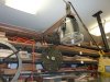
(3) My original motivation for attaching a strobe is to hollow the inside of a form relative to one of the flat, outside faces of the wooden blank. The strobe lets me freeze the relevant outside face and a laser-guided hollowing rig lets me roughly determine the relationship of the internal hollowed recess relative to the outside face by following the red dot on the outside face. Don't ask "why" I want to do this. If it comes off well, I'll post some pictures.
CONS:
(1) I get a mild headache after about 5-10 minutes of strobe work. It is the kind of headache I get when driving in bright sunlight without sunglasses for a period of time. Not a deal breaker, but not a comfortable zone to be in for a long period.
(2) The strobe I purchased for this via amazon isn’t rated for what I am doing to it. It is listed with a 10 flash/second maximum rate (although the product description on the amazon.com webpage says 15 flashes per second), but when turning a small bowl, I was going at closer to 1200 rpm, so I’m sure I am shortening the life of the flash lamp. More expensive strobes (old strobotac 1531’s, higher-end industrial equipment strobes, etc.) can go at this high rate (indeed, much higher) and adjust the brightness downwards to prolong the bulb life and reduce the perceived intensity of the light. These devices easily run more than $300. Even if you can get an old general radio strobotac on Ebay for $150 (that’s a good price, by the way), if the bulb burns out the replacement bulb goes for $375!
(3) If you don’t already own a multimeter (volt and current meter), then this is a project that you may find a bit daunting. But if you know + from - on a diagram and can read the specs on a DC power supply (voltage and current) -- this is close to the limit of what I know -- you can probably figure it out.
HOW-TO:
Here are the two key parts that I purchased for this project and how I put them together.
Stroboscope. You need a strobe light that has a “trigger” or “control” input jack on the unit. If it says “trigger”, then you are in good shape as it is designed to be hooked up to a device which sends control impulses. In my case, I took a chance and bought a “Chauvet Techno Strobe” from amazon.com for $48. In the description it says “an optional 1/4-inch mono plug from Chauvet allows for linking this model of strobe”. I correctly guessed that this linking took place via DC impulses, so I could use the phono jack input as a trigger. The cheaper strobes on amazon didn’t have inputs.
Hall-effect transistor. Basically you want a magnetic sensor that will send a DC impulse whenever a magnetic field is briefly introduced near the pickup. If you like building electronics, you can buy the hall-effect transistors for very little money. If you prefer more immediate gratification and dislike soldering, then you can buy something like a “Tol-O-Matic Magnetic Solid State Switch Sensor, PNP”. I got one on Ebay for $9.90. (Thanks to Bill Noble for the suggestion.) It is basically a three-wire cable that is attached to a small 1/4”x1/4”x3/4” metal pickup. In my case, it was rated for 3.8-25 volts DC and 400mA. You need to note these numbers when you get one and you are selecting a power supply for it.
Other stuff you probably already own:
Power supply. While you could use batteries, I have a box of old DC converters of various makes and so I looked through it to find one that was 9volts DC and 300mA. This was within the specs for the magnetic sensor, so I cannibalized it, cut off the adapter, and using my voltmeter identified + and -.
Male phono jack to fit into whatever input jack you have on the strobe. In may case, I needed an 1/4” plug. I salvaged the plug from a pair of useless old headphones. For my strobe, I determined that the tip should be the + part of the impulse and the shaft should be the - part by experimenting.
Rare-earth magnets. (In my case, I used 1/4” ones). I use one for the pickup and another one to hold the sensor onto the headstock.
Putting it together. There are three wires on the magnetic sensor. In my case, they were clearly labeled. One lead gets attached to the + end on the power source; another gets attached to the - end of the power source and also to the the minus part (shaft) of the phono jack; the third lead gets attached to the + part (tip) of the phono jack.
Testing it. The magnetic sensor should send a short impulse whenever a south-pole side of a strong magnet is placed within about 1/8” of the sensor. This will help you find the “south” side and I have labeled mine with a big “S” so I don’t need to find it again.
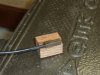
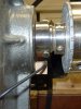
Attaching it. I took a piece of oak approximately 3/4”x3/4”x1” and notched a recess on one edge for the sensor. I glued the sensor into this edge with the correct side facing up. (In my case, the correct side has a line running along it.) I then glued another magnet with the north side facing the block into a recess I drilled on the reverse side of the oak piece. The 3/4” separation between the sensor and the attaching magnet is enough that it doesn’t seem to interfere with the magnetic sensor. Using a magnet to attach it to the headstock also allows you to easily adjust the phase of your image to get it exactly where you want it. Of course you can also slide the magnet around as well. Place your southpole-side of the magnet on the spindle and slide the sensor so that it is very close to it (1/1/6” of an inch is fine).
SAFETY:
Obviously, you do any of this at your own risk. I tell you only what I think I understand. The rest is up to you. Certainly, I am very careful not to do anything unsafe with the placement of the sensor wire. Getting tangled up with a length of wire and a lathe would be very, very bad. Also, you need to constantly remind yourself that the object is moving and not do anything absent minded like touching a seemingly-motionless object that has jagged edges.
As a first step, I tried a cheap, adjustable strobe light leftover from Halloween, but it wasn't accurate enough to stabilize the image. Instead, it produced an image drift of 2 rpm or so which was enough to make it useless for what I wanted. I realized I needed a way to synchronize the strobe light to the spindle speed exactly. I did a bit of searching on the internet and could only find reference to a Michael Mode article in Fine Woodworking many years ago on stroboscopic woodturning (issue #73, 1988?) and that article didn’t give the “how-to” advice I was looking for. Finally, I turned to the yahoo Stubby-lathe group (great group of guys, including some smart tinkerers) and I got some very useful information. With their advice, I have managed to build such a synchronized stroboscope very easily and relatively cheaply. I thought I would post my notes on the process in case others are interested.
LEGALESE: Please note that there are safety issues with using a stroboscope on a lathe, or even a stroboscope more generally (e.g., if you are epileptic). I am posting these notes only because you might find them interesting. You assume all the risks if you undertake such a project, both foreseen and unforeseen.
REASONS FOR USING A SYNCHRONIZED STROBOSCOPE:
(1) It is really fun to see in action. Seeing shavings come off a bowl while the bowl is motionless is extremely illuminating to witness once, even if you never use it again.
(2) Great device for learning tool techniques and dealing with end grain tearout. This is a benefit I never expected, but it is really nice. My previous process for dealing with end grain tearout on a bowl was to resharpen my tools and then try again and again. Failing that, I move on to a handful of other tricks (various shear scraping angles, tools, application of mineral oil or wax, etc.) Each time, I make the cut. Stop the lathe. Determine if the technique is working and how to adjust it. Try again. Stop the lathe. Etc. With a stroboscope, however, I turn it on and orient the image so that the tearout spot is visible. Then I cut with a very sharp gouge and modify the angle until the tearout starts to disappear. Just a little angle variation made all of the difference on a small holly piece I just turned, and I could find the precise angle by getting continuous visual feedback. When I got the correct angle, the torn out part suddenly had a leading edge by the gouge that was smooth and burnished-looking. Really, really cool.
(3) My original motivation for attaching a strobe is to hollow the inside of a form relative to one of the flat, outside faces of the wooden blank. The strobe lets me freeze the relevant outside face and a laser-guided hollowing rig lets me roughly determine the relationship of the internal hollowed recess relative to the outside face by following the red dot on the outside face. Don't ask "why" I want to do this. If it comes off well, I'll post some pictures.
CONS:
(1) I get a mild headache after about 5-10 minutes of strobe work. It is the kind of headache I get when driving in bright sunlight without sunglasses for a period of time. Not a deal breaker, but not a comfortable zone to be in for a long period.
(2) The strobe I purchased for this via amazon isn’t rated for what I am doing to it. It is listed with a 10 flash/second maximum rate (although the product description on the amazon.com webpage says 15 flashes per second), but when turning a small bowl, I was going at closer to 1200 rpm, so I’m sure I am shortening the life of the flash lamp. More expensive strobes (old strobotac 1531’s, higher-end industrial equipment strobes, etc.) can go at this high rate (indeed, much higher) and adjust the brightness downwards to prolong the bulb life and reduce the perceived intensity of the light. These devices easily run more than $300. Even if you can get an old general radio strobotac on Ebay for $150 (that’s a good price, by the way), if the bulb burns out the replacement bulb goes for $375!
(3) If you don’t already own a multimeter (volt and current meter), then this is a project that you may find a bit daunting. But if you know + from - on a diagram and can read the specs on a DC power supply (voltage and current) -- this is close to the limit of what I know -- you can probably figure it out.
HOW-TO:
Here are the two key parts that I purchased for this project and how I put them together.
Stroboscope. You need a strobe light that has a “trigger” or “control” input jack on the unit. If it says “trigger”, then you are in good shape as it is designed to be hooked up to a device which sends control impulses. In my case, I took a chance and bought a “Chauvet Techno Strobe” from amazon.com for $48. In the description it says “an optional 1/4-inch mono plug from Chauvet allows for linking this model of strobe”. I correctly guessed that this linking took place via DC impulses, so I could use the phono jack input as a trigger. The cheaper strobes on amazon didn’t have inputs.
Hall-effect transistor. Basically you want a magnetic sensor that will send a DC impulse whenever a magnetic field is briefly introduced near the pickup. If you like building electronics, you can buy the hall-effect transistors for very little money. If you prefer more immediate gratification and dislike soldering, then you can buy something like a “Tol-O-Matic Magnetic Solid State Switch Sensor, PNP”. I got one on Ebay for $9.90. (Thanks to Bill Noble for the suggestion.) It is basically a three-wire cable that is attached to a small 1/4”x1/4”x3/4” metal pickup. In my case, it was rated for 3.8-25 volts DC and 400mA. You need to note these numbers when you get one and you are selecting a power supply for it.
Other stuff you probably already own:
Power supply. While you could use batteries, I have a box of old DC converters of various makes and so I looked through it to find one that was 9volts DC and 300mA. This was within the specs for the magnetic sensor, so I cannibalized it, cut off the adapter, and using my voltmeter identified + and -.
Male phono jack to fit into whatever input jack you have on the strobe. In may case, I needed an 1/4” plug. I salvaged the plug from a pair of useless old headphones. For my strobe, I determined that the tip should be the + part of the impulse and the shaft should be the - part by experimenting.
Rare-earth magnets. (In my case, I used 1/4” ones). I use one for the pickup and another one to hold the sensor onto the headstock.
Putting it together. There are three wires on the magnetic sensor. In my case, they were clearly labeled. One lead gets attached to the + end on the power source; another gets attached to the - end of the power source and also to the the minus part (shaft) of the phono jack; the third lead gets attached to the + part (tip) of the phono jack.
Testing it. The magnetic sensor should send a short impulse whenever a south-pole side of a strong magnet is placed within about 1/8” of the sensor. This will help you find the “south” side and I have labeled mine with a big “S” so I don’t need to find it again.
Attaching it. I took a piece of oak approximately 3/4”x3/4”x1” and notched a recess on one edge for the sensor. I glued the sensor into this edge with the correct side facing up. (In my case, the correct side has a line running along it.) I then glued another magnet with the north side facing the block into a recess I drilled on the reverse side of the oak piece. The 3/4” separation between the sensor and the attaching magnet is enough that it doesn’t seem to interfere with the magnetic sensor. Using a magnet to attach it to the headstock also allows you to easily adjust the phase of your image to get it exactly where you want it. Of course you can also slide the magnet around as well. Place your southpole-side of the magnet on the spindle and slide the sensor so that it is very close to it (1/1/6” of an inch is fine).
SAFETY:
Obviously, you do any of this at your own risk. I tell you only what I think I understand. The rest is up to you. Certainly, I am very careful not to do anything unsafe with the placement of the sensor wire. Getting tangled up with a length of wire and a lathe would be very, very bad. Also, you need to constantly remind yourself that the object is moving and not do anything absent minded like touching a seemingly-motionless object that has jagged edges.
Attachments
Last edited:

")