-
It's time to cast your vote in the June 2025 Turning Challenge. (click here for details) -
Sign up for the 2025 AAW Forum Box Swap by Monday, June 30th (click here for details) -
Congratulations to Walker Westbrook for "Archaeological Record" being selected as Turning of the Week for June 23, 2025 (click here for details) -
Welcome new registering member. Your username must be your real First and Last name (for example: John Doe). "Screen names" and "handles" are not allowed and your registration will be deleted if you don't use your real name. Also, do not use all caps nor all lower case.
You are using an out of date browser. It may not display this or other websites correctly.
You should upgrade or use an alternative browser.
You should upgrade or use an alternative browser.
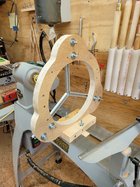
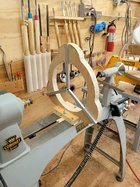
Steady rest
- Thread starter Rusty Nesmith
- Start date
Nice work! Now I have to build one……..
Thanks. I have two projects waiting, I figured it was about time.
Rusty,
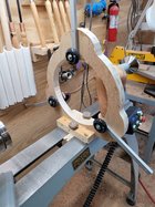
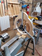
How is it secured to the lathe’s bed ways?
Rich
How is it secured to the lathe’s bed ways?
Rich
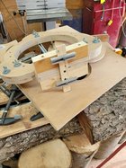
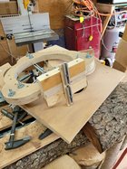
The two wing nuts on the bottom are on a 3” by 1/4-20 bolt with a 3.5” piece of track on the bottom. I drew a sharpie line on the top of the bolt with the direction of the track so I could spin it into place without having to feel underneath. I wanted to be able to put it on and take it off without having to remove the tail stock. It goes on and off in seconds.Rusty,
How is it secured to the lathe’s bed ways?
Rich
The reason for the track instead of the normal slotted board was so I can turn larger projects. I should be able to extend them out so the center of the wheel is at the first support bolt.
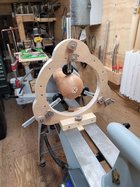
Rusty, you built a very nice steady rest. I don’t know if you use a camera or laser, but the arm at the 12 o’clock position will be in the way.
Thanks for the heads up. I forgot all about that. The bottom that connects to the bed ways is only screwed on and not glued. I did it that way in case something needed to be changed.Rusty, you built a very nice steady rest. I don’t know if you use a camera or laser, but the arm at the 12 o’clock position will be in the way.
If it's just the track that gets in the way, then you maybe able to substitute a shorter piece of track when fitting for larger pieces.
Rusty, I had the same problem when I built mine. If you can rotate the loop structure 10-15 degrees to the right on the base you should be able to avoid the problem. The laser/camera arm will be above the front of the turning where the cutting is taking place. Also you might want shorten the protruding bolts. They will find a way to snag something.Thanks for the heads up. I forgot all about that. The bottom that connects to the bed ways is only screwed on and not glued. I did it that way in case something needed to be changed.
I just checked and my laser is a few inches taller than the wood frame of the steady rest. Looks like I am good to go.
Just trying to understand. Your laser will clear the wood frame, but with the arm extended I doubt it will clear that. Am I missing something? Seems to me you need to rotate as suggested.I just checked and my laser is a few inches taller than the wood frame of the steady rest. Looks like I am good to go.
I have more track. I can make a few in different lengths. I can change that one out in under 30 seconds. That to me seems a better option than trying to rotate the whole thing.Just trying to understand. Your laser will clear the wood frame, but with the arm extended I doubt it will clear that. Am I missing something? Seems to me you need to rotate as suggested.
If it works great.
Especially if you buy an extra wheel so it can remain attached to shorter track.I have more track. I can make a few in different lengths. I can change that one out in under 30 seconds. That to me seems a better option than trying to rotate the whole thing.
Exactly. I would put a wheel on every one.
You could inlay the aluminum channels into plywood to provide additional dampening for the channels that the wheels mount to.
The lightweight channels will tend to pick up harmonic vibrations from the wheels contacting the work piece.
The rest of the steady rest looks good with plenty of mass to absorb any vibrations from the wheels.
The lightweight channels will tend to pick up harmonic vibrations from the wheels contacting the work piece.
The rest of the steady rest looks good with plenty of mass to absorb any vibrations from the wheels.
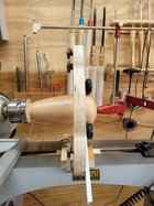
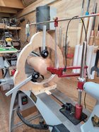
Thats pretty darn impressive piece of workFinished my steady rest. Just waiting on the wheels. I used 3/4” birch plywood and t-track for the adjustable arms for the wheels.View attachment 45195View attachment 45196
Thank you.Thats pretty darn impressive piece of work
Can you show a picture with laser/camera system in place?
Yes. I will try to get it later today.Can you show a picture with laser/camera system in place?
very nice but why didnt you make the wheels on the lathe?Finished my steady rest. Just waiting on the wheels. I used 3/4” birch plywood and t-track for the adjustable arms for the wheels.View attachment 45195View attachment 45196
I didn’t want wood wheels.
I think (hope!) that last question was a joke.
I thought it might be but you never know.I think (hope!) that last question was a joke.
@Rusty Nesmith - Hope you don't mind, but I am planning to steal your basic design 
I had acquired some inline skate wheels in very good shape some time ago, and got some parts, but then decided I did not like the design I had - seemed overly complicated to me. Yours looks like something a lot simpler. If you have any drawings or sketches you could share, I would be most appreciative. If not, the photos do a pretty decent job.
I had acquired some inline skate wheels in very good shape some time ago, and got some parts, but then decided I did not like the design I had - seemed overly complicated to me. Yours looks like something a lot simpler. If you have any drawings or sketches you could share, I would be most appreciative. If not, the photos do a pretty decent job.
I don’t mind at all. I’m sorry I don’t have any drawing or anything to share. I put two pieces of 3/4” plywood together with screws. I grabbed a compass and started to draw. I would be happy to get any measurement you might need and answer any questions you have.@Rusty Nesmith - Hope you don't mind, but I am planning to steal your basic design
I had acquired some inline skate wheels in very good shape some time ago, and got some parts, but then decided I did not like the design I had - seemed overly complicated to me. Yours looks like something a lot simpler. If you have any drawings or sketches you could share, I would be most appreciative. If not, the photos do a pretty decent job.
Thanks! Once I look at it a bit closer and draw up a plan, I may ask for some dimensions so I can scale it and adapt the sizes to fit my lathe.I don’t mind at all. I’m sorry I don’t have any drawing or anything to share. I put two pieces of 3/4” plywood together with screws. I grabbed a compass and started to draw. I would be happy to get any measurement you might need and answer any questions you have.
Hi from Canada. If you can tell me the dimensions i'll try to make one alsoI don’t mind at all. I’m sorry I don’t have any drawing or anything to share. I put two pieces of 3/4” plywood together with screws. I grabbed a compass and started to draw. I would be happy to get any measurement you might need and answer any questions you have.

