
I know this is a long post but I wanted to be thorough…
So, like many others who have the JET JWL-1642EVS; my original VFD finally spun its final spin. I went all over the place trying to find a direct replacement only to find they are obsolete. Sure, there are companies (Ali-Express) that say they sell an original, but I was skeptical. Not only are they not in the states but I was sure I would not get any assistance if the part failed, or I needed tech support.
This led me to eBay where I found a supposed, new in box, exact replacement of the original Delta VFD. I paid almost $700 and got it in a few days. Once the box arrived, I scrambled to the shop to get my lathe back up and running. I hooked the wires up the exact same way they were before disconnecting the original. Double and triple checked the wiring. Plugged it in an POW! The VFD was toast. I messaged the seller and thankfully he refunded my money. Also, of note, the bog had “big band saw” written on it in sharpie. Perhaps if I would have reset the VFD to factory I would not have had a problem but who knows. It certainly was not new.
I was not willing to repeat this situation, so I started to find out what VFD delta said was the new one. I got the part number and started my market research. The best price I found was from Digi-Key at $237.00, plus tax. After shipping and taxes, I think I paid $260. This is far less expensive than the replacement VFD from Jet (almost $1000.00). Their replacement is the E series, and it is a little less expensive than the MS300 I bought, but they would not assist with providing parameters for the new VFD.
Here is the link for the VFD I purchased from Digi-Key: https://www.digikey.com/en/products/detail/delta-electronics-industrial-automation/VFD4A8MS11ANSAA/9862546?s=N4IgTCBcDaIGoDEAiAWAggDgLIGUCMeaAcjmmiALoC+QA
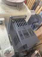
The new VFD had a slightly smaller footprint than the original, so I took a piece of aluminum plate I had laying around and made a new mount. This mount bolted straight into the factory location with some slightly longer 10-24 hex screws I bought at Ace Hardware. I also took the original 200 ohm braking resistor from the original VFD to put on this one. The new mounting plate with the standoffs allowed the resistor to mount between the head stock and the new plate with some double-sided tape. You can check your braking resistor by using a multi-meter to ensure it is reading 200ohm. If not I would replace it.
Here are the instructions for converting your Jet JWL-1642EVS from the VFD007S11A to the VFD4A8MS11ANSAA. There was a lot of trial and error getting everything to work and the one thing I could not figure out was how to get the ground to be present for both the A/C and D/C controls. I finally figured it out after moving the wire from one terminal to the other and everything working. I ended up having to splice the wire using two pigtails and a wire nut.
WARNING: I recommend programming the VFD with the motor terminals disconnected in case something goes awry. I did the bulk of the settings on the workbench with an old appliance cord I had laying around. You can simply use the cord from the lathe since everything will be disconnected from the original metal retaining plate. This plate does not hook to the new VFD.
Using the table below (110v power cord) simply connect the ground wire, black wire and white wire as specified to get power to the VFD. Once you have power, you can follow the instructions in the manual for changing parameters or watch a couple YouTube videos to get the hang of it. It is very simple to do. If I can do it… anyone can.
EDIT: THERE ARE THREE SMALL SWITCHES RIGHT ABOVE THE RED WIRE BLOCK. ALL THREE OF THEM ARE TO THE LEFT. THE LEFT MOST SWITCH MUST BY SWITCHED TO THE RIGHT TO GIVE 10V OUTPUT TO THE DCM CONTROLS.
Here are the parameters that had to be adjusted for the VFD to control everything correctly.
Now that you have all the parameters set you are ready to mount the new VFD to the lathe. Below is a table showing which factory wires go to each terminal to get everything going correctly. Like I said above I used the original braking resistor on the new VFD. This is necessary since you are going to use the VFD to slow the lathe by retarding the motor slightly with reverse current. At least I think that is how it works.
There are three tables, one for the control wires, one for the high voltage wires (110V) and one for the wires to the motor. I recommend connecting the wires in the order they are listed in the table, so you are not fumbling around the others once installed. Do not connect the power until everything is connected to the VFD and you have double checked it all.


Once everyting is connected and you have double and triple checked put on all covers and prepare for the first run.
Plug in the power cord and check each function to ensure they are all working. Power on, RPM up, RPM down, forward and finally reverse. I recommend allowing your lathe to come to a stop before switching directions.
I hope I haven’t missed anything and this helps others get their lathe up and running. I am available to answer any questions you may have.
GO MAKE SOME SHAVINGS…
John M. Hebdon, MSgt, USAF (retired)
So, like many others who have the JET JWL-1642EVS; my original VFD finally spun its final spin. I went all over the place trying to find a direct replacement only to find they are obsolete. Sure, there are companies (Ali-Express) that say they sell an original, but I was skeptical. Not only are they not in the states but I was sure I would not get any assistance if the part failed, or I needed tech support.
This led me to eBay where I found a supposed, new in box, exact replacement of the original Delta VFD. I paid almost $700 and got it in a few days. Once the box arrived, I scrambled to the shop to get my lathe back up and running. I hooked the wires up the exact same way they were before disconnecting the original. Double and triple checked the wiring. Plugged it in an POW! The VFD was toast. I messaged the seller and thankfully he refunded my money. Also, of note, the bog had “big band saw” written on it in sharpie. Perhaps if I would have reset the VFD to factory I would not have had a problem but who knows. It certainly was not new.
I was not willing to repeat this situation, so I started to find out what VFD delta said was the new one. I got the part number and started my market research. The best price I found was from Digi-Key at $237.00, plus tax. After shipping and taxes, I think I paid $260. This is far less expensive than the replacement VFD from Jet (almost $1000.00). Their replacement is the E series, and it is a little less expensive than the MS300 I bought, but they would not assist with providing parameters for the new VFD.
Here is the link for the VFD I purchased from Digi-Key: https://www.digikey.com/en/products/detail/delta-electronics-industrial-automation/VFD4A8MS11ANSAA/9862546?s=N4IgTCBcDaIGoDEAiAWAggDgLIGUCMeaAcjmmiALoC+QA
The new VFD had a slightly smaller footprint than the original, so I took a piece of aluminum plate I had laying around and made a new mount. This mount bolted straight into the factory location with some slightly longer 10-24 hex screws I bought at Ace Hardware. I also took the original 200 ohm braking resistor from the original VFD to put on this one. The new mounting plate with the standoffs allowed the resistor to mount between the head stock and the new plate with some double-sided tape. You can check your braking resistor by using a multi-meter to ensure it is reading 200ohm. If not I would replace it.
Here are the instructions for converting your Jet JWL-1642EVS from the VFD007S11A to the VFD4A8MS11ANSAA. There was a lot of trial and error getting everything to work and the one thing I could not figure out was how to get the ground to be present for both the A/C and D/C controls. I finally figured it out after moving the wire from one terminal to the other and everything working. I ended up having to splice the wire using two pigtails and a wire nut.
WARNING: I recommend programming the VFD with the motor terminals disconnected in case something goes awry. I did the bulk of the settings on the workbench with an old appliance cord I had laying around. You can simply use the cord from the lathe since everything will be disconnected from the original metal retaining plate. This plate does not hook to the new VFD.
Using the table below (110v power cord) simply connect the ground wire, black wire and white wire as specified to get power to the VFD. Once you have power, you can follow the instructions in the manual for changing parameters or watch a couple YouTube videos to get the hang of it. It is very simple to do. If I can do it… anyone can.
EDIT: THERE ARE THREE SMALL SWITCHES RIGHT ABOVE THE RED WIRE BLOCK. ALL THREE OF THEM ARE TO THE LEFT. THE LEFT MOST SWITCH MUST BY SWITCHED TO THE RIGHT TO GIVE 10V OUTPUT TO THE DCM CONTROLS.
Here are the parameters that had to be adjusted for the VFD to control everything correctly.
| Parameter | Function | Factory Setting | Adjusted Setting |
| 00-20 | Master Frequency Command Source | 0 | 2 |
| 00-21 | Operation Command Source | 0 | 1 |
| 00-29 | LOCAL/REMOTE Selection | 0 | 2 |
| 02-00 | Maximum Operation Frequency | 60 | 132 |
| 02-02 | Output Voltage of Motor 1 | 220 | 230 |
| 02-03 | Mid-point frequency 1 of motor 1 | 3.00 | 5.00 |
| 02-04 | Mid-point Voltage 1 of Motor 1 | 11 | 20 |
| 02-05 | Mid-point frequency 2 of motor 1 | 1.5 | 5.00 |
| 02-06 | Mid-point Voltage 2 of Motor 1 | 5 | 20 |
| 02-12 | Acceleration Time 1 | 10 | 5 |
| 02-13 | Deceleration Time 1 | 10 | 5 |
| 05-02 | Rated Power for induction motor 1 (kw) | ~ | 1.1 |
| 05-03 | Rated Speed for induction motor 1 | 1710 | 1720 |
Now that you have all the parameters set you are ready to mount the new VFD to the lathe. Below is a table showing which factory wires go to each terminal to get everything going correctly. Like I said above I used the original braking resistor on the new VFD. This is necessary since you are going to use the VFD to slow the lathe by retarding the motor slightly with reverse current. At least I think that is how it works.
There are three tables, one for the control wires, one for the high voltage wires (110V) and one for the wires to the motor. I recommend connecting the wires in the order they are listed in the table, so you are not fumbling around the others once installed. Do not connect the power until everything is connected to the VFD and you have double checked it all.
| 110v power cord | |
| Green wire with ring connector | Grounding screw on far left |
| Black wire | L1 |
| White wire | L2 |
| Control Wires: | |
| These wires are coming from the headstock | |
| Red wire with ring connector | L1 with the black wire from the 110v power source |
| Tan wire with ring connector | L2 with the white wire from the 110v power source |
| Yellow wire | 10 |
| Blue wire (pigtailed) SEE IMAGE | One to ACM and one to DCM |
| Green wire | AVI |
| White wire | MI1 |
| Black Wire | MI2 |
| Break resistor 2 black wires with ring connectors | B1 and B2 (there is no polarity) |
| Motor Wires: | |
| Green Wire with ring connector | Grounding screw on far right |
| Red wire | T1 |
| Black wire | T2 |
| White wire | T3 |
Once everyting is connected and you have double and triple checked put on all covers and prepare for the first run.
Plug in the power cord and check each function to ensure they are all working. Power on, RPM up, RPM down, forward and finally reverse. I recommend allowing your lathe to come to a stop before switching directions.
I hope I haven’t missed anything and this helps others get their lathe up and running. I am available to answer any questions you may have.
GO MAKE SOME SHAVINGS…
John M. Hebdon, MSgt, USAF (retired)
Attachments
Last edited:
