• Beware of Counterfeit Woodturning Tools (click here for details)
  • Johnathan Silwones is starting a new AAW chapter, Southern Alleghenies Woodturners, in Johnstown, PA. (click here for details)
  • Congratulations to Jim Hills for "Journey II" being selected as Turning of the Week for May 6th, 2024 (click here for details)
  • Welcome new registering member. Your username must be your real First and Last name (for example: John Doe). "Screen names" and "handles" are not allowed and your registration will be deleted if you don't use your real name. Also, do not use all caps nor all lower case.

Vacuum Chucking System Chucking Optomization

For Vacuum Chucking Systems,which areas do you want to have the most emphasis??

  • Other?

    Votes: 0 0.0%

  • Total voters
    22
  • Poll closed .
Joined
Mar 11, 2011
Messages
82
Likes
0
Location
Fort Collins, CO
In reading through the posts on this forum and reading aritlcles on the web, I have seen a lot of good information on building vacuum chucking systems and some good techniques for using them. Since I wrote the article on vacuum chucking in the February 2011 issue in the AW, the comments and questions I have had leads me to the conclusion that some people are satisfied if the bowl just stays on and they can finish it off. Then there are those of us that want to understand how the system works, how to fix problems and to get the most performance out of the system, and then there are those that fit inbetween. I have not been able to find much published information on vacuum chucking systems that go much beyond just turning them on start using them. This thread is for those that want to understand their vacuum systems and optomize the performance. Note: if you haven't found them there are a couple of other threads on this forum on these topics.
A vacuum chucking system is just that , it is a system. To understand the system, we need to know how the individual parts work and interact with each other.
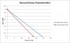
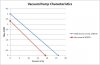
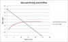
I plan on starting with vacuum pumps, the different types, characteristics and the pros and cons of each, the performance curves and what they mean, and how the curves change with pump wear and usage.
I will then move onto the other components of the system and describe their characteristics and interactions.
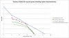
Inorder to optomize performance, we need to be able to measure what the system is doing before and after any changes to see if we really did make a change and it it was in the right direction. The measuring tools to be used are simple and cheap. Some you already have, a vacuum gauge, and the other one you can easily build. And of course, I'll show you how to use them.
In the spirit of full disclosure, I am in the process of developing several articles and maybe a book on vacuum chucking systems. Your comments and questions will help me to better explain the concepts I am presenting and at the same time I hope that I will help you to under stand and resolve some of your questions and concerns. If I write something you don't understand or agree with, then lets discuss it. So let the questions flow.
To be continued ....
John Giem
 

john lucas

AAW Forum Expert
Joined
Apr 26, 2004
Messages
8,346
Likes
3,602
Location
Cookeville, TN
I look forward to seeing what you put together. I've assembled 2 systems, one home built from a car compressor and one using a Ghast pump I bought at the flea mkt. I had to pull information from a lot of different articles and it would be really nice to have that info and more in one comprehensive source that people could find.
I use my vacuum chuck for all sorts of things. Turning bottoms is probably the most used but I've used it to save a lot of turnings that had problems and there would not have been any other way of holding them.
 
Joined
Jul 21, 2011
Messages
3
Likes
0
Location
Lenoir City, TN
I am looking forward to the thread. Have a One Way system and an old, wornout, Gast pump. I need to find parts to rebuild or just replace it.
 

Bill Boehme

Administrator
Staff member
Beta Tester
TOTW Team
Joined
Jan 27, 2005
Messages
12,903
Likes
5,193
Location
Dalworthington Gardens, TX
Website
pbase.com
I am looking forward to the thread. Have a One Way system and an old, wornout, Gast pump. I need to find parts to rebuild or just replace it.

Finding parts is no problem at all. Just go to a Gast distributor or to Gast and give them the model number. The design of their rotary vane pumps has not changed much, if any, for a very long time. Rebuilding is a snap -- just get the overhaul kit and follow the instructions to disassemble and replace old parts. The problem usually amounts to crud build up inside the pump and worn vanes. There is also a flush that you are supposed to run through the pump periodically, but I suspect hardly any woodturner ever do it or have read their owner's manuals about regular maintenance.
 
Joined
Mar 11, 2011
Messages
82
Likes
0
Location
Fort Collins, CO
Vacuum Pumps

Before we can optomize or improve our vacuum systems, we need to be sure everyone is up to speed, at least on the major components. Most of the vacuum pumps used for vacuum chucking are referred to as positive displacement pumps. For each rotation of the shaft in free air, the volume of the air moved is known. The pump types are diaphram, piston and rotary vane. The piston and rotary vane pumps can be oilless or with oil. For these two types of pumps, the pumps using oil will pull a higher vacuum than the oilless. The oil provides additonal sealing within the pumps. Rotary vane pumps are quite popular since they run quiet and give good performance. A word of caution, be aware that some,not all, of the rotary vane pumps that run with oil have an objectionable amount of oil in the exhaust air and you may want to give the exhaust special attention.
Even though we use filters before our pumps, some fine dust may get through and into the pump, the oil pumps will be more likely collect that dust over time and will need to be cleaned out.
Each of the three types of pumps have slightly different abilities when it comes to the maximum vacuum they can pull. The rotary vane pumps will pull the highest, followed by the piston pumps with the diapharam pumps the lowest. Luckly, the differences between the maximum vacuum is not a big deal for woodturners.
The way that the pumps are designed, the diaphram and pistion pumps have need for check valves that control the direction of the air flow. Generally, when the pump is turned off, they will hold the vacuum. The rotary vane pumps do not need the reed valves to work so when you turn them off, they will allow the air to bleed back.
Another concern is moisture, wood sap, water, etc. The diaphram and dry (oilless) pumps will tolerate moisture more than the oil pumps. Granted, the dry pumps will crrode if not dried out but they are easier to clean up than those that use oil. When water gets into the pump oil, it makes the oil turn milky, This may be seen in the oil level sight glass. This is why Gast has an elaborate shut down proceedure that some Turners have questioned. By following their shutdown proceedure, most of the water can be eliminated. If any moisture is allowed to set in the pump, we run the risk of corrosion and ruining the pump.
What do the pump specifications mean? There are two basic specifications that are usually given, the maxumum vacuum and the free air flow rate. The free air flow rate is the amount of air that will be moved through the pump when nothing is connected to the input or the output. The maximum vacuum is what will be developed if the input is blocked off. Due to design differences, the maxumum vacuum will vary between the different types of pumps.
I have attached a file, Ideal Vac Pump.jpg, that illustrates the performance of an ideal pump. Along the bottom is the vacuum measured at the vacuum pump. If the input is blocked off, zero flow, then the maxumum vacuum is generatedsa. Likewise, with nothing connected, the vacuum will be zero and the max flow will occur, 4 SCFM. But in the real world, we seldom operate under these conditions, so what happenes inbetween? If you put a restriction on the input and starve the pump for air, the vacuum level will increase. By measuring the flow rate of the air and the resulting vacuum level, it will make a straight line between the two points. Rmember this is an ideal pump so the line is straighter than for a real pump. With this chart, if you know the vacuum level, then you know the flow rate and if you know the flow rate then you know the vacuum level.
With usage the pump over time will develope some leakage around the piston, around the vanes, pin holes in the diaphram, the valves may leak, etc. The main effect is the reduction of the maxumun vacuum generated and being slow to reach that maximum level.
The specifications for the vacuum pumps are developed/measured at Standard Conditions, i.e. sea level and a standard temperature. I live in Northern Colorado at an altitude of 5000 ft. The pump specifications need to be adjusted for altitude. Air pressure drops about 1 in Hg for every 1,000 feet, so my maximum vacuum will be lower by about 5 in Hg. (the numbers on the chart are a bit off.) Likewise, the volume of air moved must also be adjusted. Since air is compressable, a baloon with one cubic foot of air collected at 5000 feet will be compressed and get smaller at sea level. The baloon will contain the same mass of air and the same number of molecules but the volume will be smaller. To minimize confusion between users at different locations, all volumes measured are adjusted to standard conditions. One cubic foot of air (1CFM) collected at 5000 ft. will be compressed to about 0.828 SCFM (at sea level).
Weathermen do the same thing with the weather charts. All barometer readings are adjusted for altitude so that they 'look like' they were taken at sea level.
But John, measuring vacuum levels is easy, I just use my vacuum gauge. How do I measure the air flow rate?
To be continued.....
 

Attachments

  • Ideal Vac Pump.jpg
    Ideal Vac Pump.jpg
    61.5 KB · Views: 34
  • VAc Pump, altitude.jpg
    VAc Pump, altitude.jpg
    63 KB · Views: 28
Joined
Apr 3, 2006
Messages
142
Likes
11
Location
Abilene, Texas
Pump question

In looking at the graph on the ideal pump it says 4.5 is the ideal. My pump is a gast and does 8 scfm. Have I made a mistake?

Ed
 

Bill Boehme

Administrator
Staff member
Beta Tester
TOTW Team
Joined
Jan 27, 2005
Messages
12,903
Likes
5,193
Location
Dalworthington Gardens, TX
Website
pbase.com
In looking at the graph on the ideal pump it says 4.5 is the ideal. My pump is a gast and does 8 scfm. Have I made a mistake?

Ed

It just means that you have a bigger vacuum pump that has a greater open-port flow rate than the typical 1/3 HP Gast rotary vane pump.

I suspect that there may be a different interpretation of what the word "ideal" means when used by an engineer vs. the way that a layman uses the word. In the engineering sense, the word ideal means that the data shown represents what would be the maximum performance from the vacuum pump in perfect condition and represents what is the best attainable performance for that particular model pump. My gut feel is that your interpretation of ideal is that a vacuum pump having an open port flow rate of 4 CFM is the optimal value -- and that is not the case at all. Your size vacuum pump is just fine.

Ideal is a condition that we would rarely encounter in the real world unless talking about a brand-new never-previously-used item and even then the performance is not likely to match up with a perfect "ideal" unit.
 
Last edited:
Joined
Mar 11, 2011
Messages
82
Likes
0
Location
Fort Collins, CO
In looking at the graph on the ideal pump it says 4.5 is the ideal. My pump is a gast and does 8 scfm. Have I made a mistake?

Ed

Ed, Bill's description of 'ideal' is right on target, and yes I am an engineer. Another factor, is that a 'real' pump's performance is not a straight line but it is close to one if there are no defects. Using a straight line to represent the pump makes the description simpler. I thought about not using numbers but just labels instead. Using my wife as an example, she needs numbers for her to follow and understand. An other related question often asked is "What vacuum pump should I use in my system?" In most cases, use the one you already have is the best pump to use. It is just a matter making sure that you are getting the best performance from it.
I appreciate your question in that it keeps me 'calibrated' to the non-engineers out there.
John
 
Joined
Mar 11, 2011
Messages
82
Likes
0
Location
Fort Collins, CO
Measuring air flow rate

In trying to understand the operation of our vacuum systems, we need to be able to estimate two parameters of its operation, the vacuum levels and the flow rate of the air within it. It is relatively easy to measure the vacuum levels. We only need to connect a vacuum gauge and read the number. Well, not quite, unfortuneately, gauges most of us use are not calibrated. This means that if you connect several of these gauges together at one time and compare the readings for different vacuum levels, they will not all read the same. This leads to uncertainty in the true vacuum level. Just be aware of the existance of this uncertainty, it is small enough that we can ignore it in most cases. We will need to be careful and use the same gauge for all of our vacuum readings we collect.
To keep the measurement costs down so that we can afford to make measurements, we will use an orifice to measure the flow rate(s). An orifice is nothing more than a hole drilled through a metal plate. In general, if we know what the difference in pressure (vacuum) is across the plate from one side to the other, then we can determine the flow rate of the fluid (air) going through the orifice. In the literature and on the web, there are many tables available that given the diameter of an orifice and the vacuum drop across the plate, the rate of flow is listed. (Google 'orifice air flow'). Attached is a chart showing the characteristics of air flowing through an orifice as a function of the vacuum across it. The curve shows that as the vacuum across the orifice increases the flow also increases up to the point where the speed of the air causes turbulant air flow (ripples or waves) resulting in a constant rate of flow for all vacuum levels beyond that point. (Your gas bar-b-que grill uses this principle to control the flow of propane into the burner.) If we measure the vacuum across the orifice then we can use the chart to tell us the rate of air flow through the orifice. Example, if the vacuum across the orifice is 5 in Hg, then the flow through it is about 1.6 CFM.
Now if we are smart enough, we can use the orifice to control the air flowing into our vacuum pump. By measuring the vacuum across the orifice we can look up the corresponding flow through the orifice. Since there is nothing between the pump and the orifice, in this case, the the vacuum level and flow are the same for both the pump and the orifice. If we plot the pump characteristics and the orifice characteristics on the same graph, then where the two lines cross is the 'solution' or point of operation. The second graph I have attached has both plotted. The two lines cross at 12 in Hg, indicating that the flow of air is 2.1 SCFM.
By applying different size orifices in the above setup, we can plot different points along the pump characteristic line and determine the pump's performance. This appears to be a lot of work to measure these performances. I'll show you later how to make this an easy task. In the real world, our turning (with leakage) will replace the orifice. Then all that stuff between the vacuum chuck and the pump will also have an effect. I will be showing you how to determine your system's performance relative to what your pump can deliver. then we can make improvements in our system and actually measure the resulting improvements. In the past, we made certain changes and just hoped it would work better but could not prove or measure the improvement. You will soon be able to verify that the changes were beneficial and by how much.
To be continued ...
John Giem
 

Attachments

  • Orifice Characteristics.jpg
    Orifice Characteristics.jpg
    53.2 KB · Views: 15
  • Vac Pump and orifice.jpg
    Vac Pump and orifice.jpg
    58.3 KB · Views: 16
Joined
Mar 11, 2011
Messages
82
Likes
0
Location
Fort Collins, CO
Improving the System

If our turnings we put on the vacuum chuck never leaked it would make things a lot easier. But they often do leak, we can see this by the reduced reading on the vacuum gauge. With the air flowing through our system, the vacuum levels will change as we move from the pump out to the chuck. Where you put your vacuum gauge is important. What we are really interested in is the vacuum within the vacuum chuck. The air flowing through the system causes losses with each component it flows through. So, to optomize the performance of our vacuum systems, we want to do two things. First reduce as much leakage within the system as possible. This leaves as much as the pump capacity available for holding our turning onto the vacuum chuck. Second, recognizing that we will have some leakage, we want to reduce changes in vacuum as the air moves through out system.
Tracking down leakage was covered im my article in the Feb 2011 issue of the AW. Here we will start looking at how to evalate losses due to flow and how to reduce them.
I ran most of my tests with the lathe off with the assumption that the losses through the rotary vacuum adapter would not change with the lathe running. This allowed me to drill and tap a hole in the side of my vacuum chuck and make measurements of the vacuum within the chuck. I used the same 4 1/2" vacuum gauge for for all measurements. For measureing flow I made myself an orfice plate with a large number of three different sized orifices. The plate was sized to fit on a vacuum chuck made from a 4 inch PVC coupling. I used a drill press to make the holes as smooth and crisp as possible. The holes for the orifices should be seperated enough so that they do not interact in usage which would disrupt the air flow and test results. I used multiple layers of black electrical tape to seal off all unused orfices. One layer was not sufficient for some of the larger orifices. During the tests, the orifice plate was placed on a vacuum chuck and with the pump running the tape was removed from the orifices a few at a time. The vacuum was recorded in an Excell spreadsheet along with the number and sizes of the open orifices. The flows were then calculated and plotted.
The attached graph is repsentative of the measurements I have collected. The pump is used and I am planning on rebuilding it. It is a two piston pump. The blue line is the specification for the pump given by the manufacturer. The red line is the performance of the pump as I measured it. Keep in mind that all of these measurements are uncalibrated so there is an unknown accruacy in the numbers. But if we use the same vacuum gauge and orfice plate for each measurment, the the shape of the curves and the changes from measurement to measurement are very useful. At the maxumun vacuum point, the vacuum achieved was about 19 in Hg. Part of the decreased level is due to the altitude of 5000 feet and part is due to leakage from worn parts. Another indicator of the presence of the leakage was the very slow atainment of the final vacuum level.
For most of my tests, I stop when the vacuum level reaches about 5 in Hg for two reasons. First, I don't use the system below 5 in Hg and second, it is difficult to get accurate readings with the gauges I have below 5 in Hg.
I connected the vacuum pump to a system with filter, valves, tubing, manifold, rotary adaptor, etc. and measured the performance using the same techniuqes as before, vacuum gauge at the chuck and the orifice plate on the chuck. The performance of the system was significantly different from the pump alone, See chart. At low flow levels, the losses were small and tracked closely but as the flow increased the vacuum dropped and diverged from the pump performance. For example, when the leakage increased to the point where the vacuum dropped to 10 in Hg, it only took a leakage of about 1.7 SCFM whereas the pump by itself would have pumped about 2.7 SCFM.
Looking at it another way, consider the vacuum at the chuck for a leakage of about 1.9 SCFM. For the oiginal system, the vacuum at the chuck would be 6 in Hg for the original system and about 12 in Hg after improvements. This difference is due to the hardware between the pump and the vacuum chuck restricting or sarving the flow of air from the chuck to the pump. Note that a vacuum gauge located at the pump would not see the same levels as measured at the chuck.
Upon seeing how much the system 'degraded' the performance, I set out to improve it. The third line shows the improvement is the system as a result of my improvements.
The significance of this is that a bowl that is too leaky to mount and hold with the original system can be mounted on the improved system. Another way to state this is that the improvements gave me more margin in the operation of my system.
The second graph is an attempt to compare the performance of the original to the improved system relative to the pump alone. In general the graph shows that the original system had about twice the losses than the improved system.
Unstated but implied, the leakage of this system was tested before any of these tests were run and it was small enough to be negligable. In the next installment I will go through what changes I made to improve the performance. A challenge for you is to come up with some ideas that can be used to enhace the system performance.
To be continued ...
John Giem
 

Attachments

  • Vac Pump in Systems.jpg
    Vac Pump in Systems.jpg
    95.4 KB · Views: 18
  • percent losses & improvement.jpg
    percent losses & improvement.jpg
    78.6 KB · Views: 17
Joined
Mar 11, 2011
Messages
82
Likes
0
Location
Fort Collins, CO
Improving vacuum system flow rates

I think that most of us have the same idea about what is in a basic vacuum chucking system. But as a review, starting at the pump....
-pump, will have the max vacuum in the system, vacuum level depends upon air flow rate. How starved is the pump for air?
- A hose barb is screwed into the pump and a hose is connected to the hose barb.
- the hose goes to another hose barb wich is connedted to the filter.
- at the other end of the filter is another hose barb and hose which runs to the hose barb connected to the manifold.
- the manifold usually has the vacuum gauge and control valve, at the output is another hose barb connected to another hose.
- The hose runs to another hose barb that is connected to the rotary vacuum adapter.
-the vacuum adapter is connected to the outboard end of the spindle
- the inboard end of the spindle has the vacuum chuck mounted on it.

In summary, we have several feet of hose, six hose barbs, the manifold, the filter and the rotary vacuum adapter. In the ideal case, we do not have any leakage when we put a bowl on the chuck. If there is no leakage, there is no air flow and there is no vacuum drop. But in the real world, there is leakage and there is air flow back to the vacuum pump. If you put seveal vacuum gauges in different places in the system, you will see that the largest vacuum is at the pump and it decreases as we move toward the vacuum chuck which will have the least vacuum in the system. To understand what causes the losses lets look at water hoses. We have all seen that a large diameter hose delivers more water than a small diameter hose. As water flows through the hose, it rubs against the walls of the hose usually in what is called laminar flow. When the water goes through a connector, the sides of the passage are not flat and smooth causing the water make waves and eddies, i.e. turbulence. When looking at the vacuum system, there are losses due to turbulance and friction in many places; each connector, bend in the path, the hoses, etc.
Now to what did I do to improve the system performance in the last post. First my briliant idea of using quick disconnets in the system proved to be a bad idea. They produced a significant loss, so I got rid of them. Next was the hoses, they were longer than really needed and they had 1/4" ID (inside diameter). I got rid of the quick disconnects, changed the hoses to 3/8" ID along with the hose barbs. Compare the inside diameter of a connector for 1/4" hose to that of a 3/8" hose. The smaller diameter of the 1/4" connector will cause more losses than the 3/8". Another place to look is the diameter of the hole passing through the rotary vacuum adapter. I have seen adapters ranging from 1/8" to over 3/8". The worst thing about the adapter with the 1/8" passage was the 1/8" hose that was supplied with it. From this experience, I have two remommendations:
1. when building up a new system;
- It is OK to use 1/4" pipe fittings and connectors, they have a relatively large passage way.
- Use 3/8" hose or larger for those main paths that are carrying the air from the chuck to the pump.
- Look for a rotary vacuum adapter that has the largest diameter bore through it.
- avoid unnecessary fittings and connectors. Each bend and transistion cuses losses.
- recognize that the maximum flow available through the system is more dependent on the system hardware than pump capacity. That is, buying the biggist pump you can find may be futile if you don't have adequate hardware.

2. If you already have a vacuum system built up and in use, don't panic but do the following:
- evaluate how well your current system performs relative to your needs.
- If improvement is needed or desired, the look for the most likely cause of restrictions in the system and replace them one at a time picking the 'worst' one each time.
- only change what is needed to get the performance you need/want.

Remember that there are a lot of very useful and productive systems in usage that are 'less than perfect'.
 
Joined
Mar 11, 2011
Messages
82
Likes
0
Location
Fort Collins, CO
What can you do besides finishing up bowl bottoms?

What can a vacuum chucking system be used for beside finishing up bowl bottoms? There seem to be a lot of inerest in this question. I'm going to start a list of uses that primarily depend upon the vacuum system that I have seen or have done. I would like for you Readers to add to the list.
1. Finishing off the bottom of a turning.
2. Turning coasters and trivets. (I only use the vacuum chuck and live center)
3. Offset inlay turning
4. The Compliant Vacuum Mandrel and Chuck can mount and hold most any turning blank. See the thread 'Update on Vacuum Chucking Systems'.
5. ???


Now the challenge if for you to add to the list.
 
Joined
Nov 8, 2011
Messages
27
Likes
0
Location
Tucson AZ
I actually just purchased my first Vacuum chuck last week. I got the Oneway, later to find out, I need the swivel piece that goes into the end. Wasn't expecting to have to spend another hundred bucks. With the oneway, the hand wheel has to be removed. Is there any other that could be recommended that I could leave the wheel on?

A detailed diagram that breaks it down into what comes with a purchase and what additional parts needed. That would help prevent others from encountering additional expenses when purchasing a chuck. Thanks for all your effort.
 
Last edited:
Joined
Jun 10, 2004
Messages
792
Likes
9
Location
Ames, Iowa (about 25 miles north of Des Moines)
Website
rwallace.public.iastate.edu
I actually just purchased my first Vacuum chuck last week. I got the Oneway, later to find out, I need the swivel piece that goes into the end. Wasn't expecting to have to spend another hundred bucks. With the oneway, the hand wheel has to be removed. Is there any other that could be recommended that I could leave the wheel on?

Bill:

You might want to check-out Tom Styers' vacuum adapters which are very well made and are designed to fit onto the lathe without the need to remove the handwheel. Have a look at his web site for JT Turning Tools HERE. [Note: Although Tom is a friend, I have no financial interest in this company!]

I actually have used the Oneway Vacuum Adapter for many years (and love it!), which replaces the hand "wheel" on the Jet 1642 lathe - installing it is no big deal, but leaving it on the lathe all the time means you lose the ability to use a knock-out rod for taper-mounted centers. Tom's adapters are easily removed which enables use of the original handwheel, and will permit using a knock-out rod without further hassle.

A detailed diagram that breaks it down into what comes with a purchase and what additional parts needed. That would help prevent others from encountering additional expenses when purchasing a chuck. Thanks for all your effort.

There are MANY sources of information available on the web about what components you need to set-up a vacuum chucking system. I don't understand what the problem is when you purchased a vacuum chuck - I believe it's quite apparent that you are buying the chuck (only) when sold as such, and not the components of an entire system. I don't consider this Oneway's problem, as each of their items is very clearly marked as to what you are getting. (I own two of their vacuum adapters and three different sized Oneway aluminum chucks, which are very well made.) A vacuum chuck is just that, a chuck, and nothing more. It sounds to me like your interpretation of what you thought of as a "chuck" is in your definition more like a 'chucking system'. In actuality, the former is only one component of the latter.

If you need additional information about setting-up a vacuum chucking system, there are a few links located HERE to get you started - there are likely others also now available which I have not yet added to my Woodturning Links page. ( I sometimes wish for 36 hour days...)

"Once you go VAC, you'll never go back."

Rob Wallace
 
Joined
Mar 11, 2011
Messages
82
Likes
0
Location
Fort Collins, CO
Bill:

You might want to check-out Tom Styers' vacuum adapters which are very well made and are designed to fit onto the lathe without the need to remove the handwheel. Have a look at his web site for JT Turning Tools HERE. [Note: Although Tom is a friend, I have no financial interest in this company!]

Rob Wallace

The JT Turning Tools vacuum adapter only plugs into the outboard spindle on the Powermatic 3520 lathe. It is one of the few that have a controled bore in the outer spindle. Tom uses a replacement handwheel on all other lathes. The handwheel is fitted to the external threads, similiar to the OneWay, and provides a bore the same size as the 3520. This allows the usage/stocking one rotary adapter and mulitple handwheels that will fit most lathes. OneWay has internal O-rings for sealing but must be removed, unscrewed, to use the knockout bar. The JT Turning Tools adapter, uses O-rings on a shaft that just plugs int the end of the new handwheel or spindle on the 3520.

There are rotary vacuum adapters (see Craft Supply) that cost about half of the two mentioned above. The use a threaded piece of pipe that goes through the spindle and a screw on flange on the inboard end of the spindle. The ones I have looked at seem to work but be aware of several 'design features'. These adapters usually have rather small vacuum connections which would limit the air flow. You would need to provide some method a sealing the flange and threads on the inboard end. It is more work to install and remove each time. You can not use any lathe accessories that are inserted into the spindle while the adapter is in place. (Yes, I'm biased.)

I hope that this helps.
John Giem
 
Back
Top